How Do You Install A Switchgear Voltage Indicator?
Mount a Switchgear Voltage Indicator safely by following expert steps for capacitive dividers, coaxial cables, and LRM system testing.
Essential Safety Protocols Before Beginning Installation
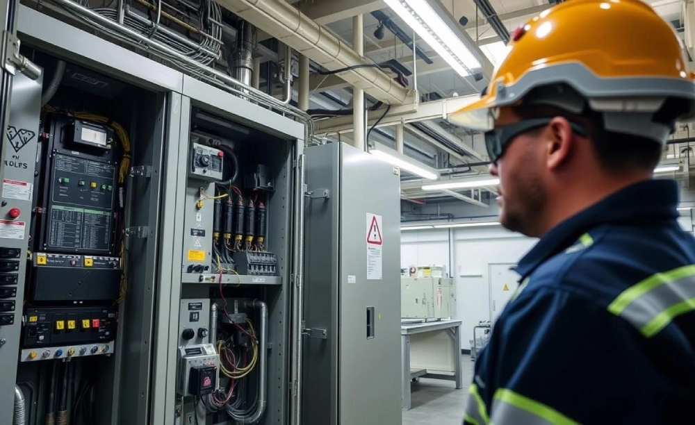
Electrical safety dictates rigorous preparation before physical mounting begins. Operators must isolate the medium-voltage cubicle completely. Grounding switches must secure all active incoming feeders. Technicians verify the dead state using approved testers. A Switchgear Voltage Indicator ensures the safety of medium-voltage maintenance. It continuously monitors the presence of voltage across all three phases. Proper personal protective equipment remains mandatory during this initial phase. Arc flash suits and insulated gloves shield personnel from hazards. Engineers must review the specific wiring schematic of the cubicle. This preliminary review prevents critical wiring errors during mounting. Only certified technicians should perform these highly specialized electrical procedures. Standard practices require double-checking every step to avoid accidents. Voltage detection systems function reliably only when you install them under safe conditions.
Selecting the Correct Switchgear Voltage Indicator for Your System
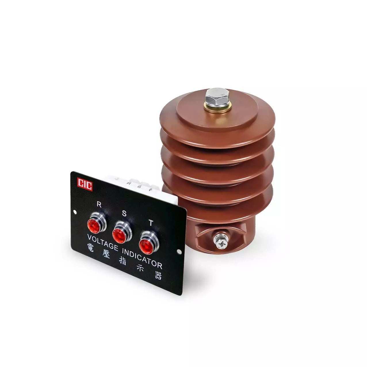
System specifications dictate the choice of the appropriate monitoring device. Engineers must identify the system voltage class before buying components. Most medium-voltage installations utilize capacitive dividers to step down the signal. These dividers must match the input capacitance of the display device. IEC standards define the parameters for voltage detection systems very clearly. Compliance with international standards guarantees reliable long-term performance in hazardous environments. You must verify if the panel requires a continuous indicator. Some retrofits use plug-in portable indicators instead of fixed units. Modern panels usually benefit from front-facing LED screens for immediate readings. Clear optical signals help operators quickly verify the system state. Always choose high-quality components from reputable manufacturers to maintain panel integrity. Correct selection prevents damage to sensitive electronic components inside the panel. This decision directly affects the overall safety of your substation
Mount the Coupling Electrode Within the Cable Compartment
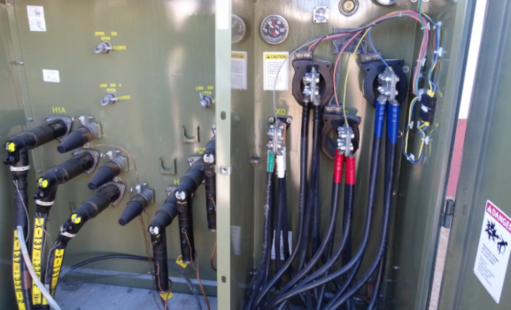
Physical installation starts inside the primary cable compartment of the switchgear. Workers must install capacitive coupling electrodes on each busbar phase. High-voltage insulation sleeves must protect these sensory connections from flashovers. Proper spacing between phases prevents dielectric breakdown during peak surges. Technicians connect the main display to the sensor outputs. Grounding the mounting bracket ensures absolute safety for the electronic circuits. Coaxial connectors must attach firmly to prevent loose contact issues. Excessive humidity or dust can degrade the signal over time. Therefore, use robust protective covers over all exposed sensor terminals. Safe clearance distances must strictly comply with regional utility regulations. Installers should document the exact electrode spacing for future maintenance audits. Meticulous electrode placement guarantees accurate voltage readings under load variations. This physical stage forms the foundation of the whole monitoring system.
Connect the Coaxial Cables to the Indicator Unit
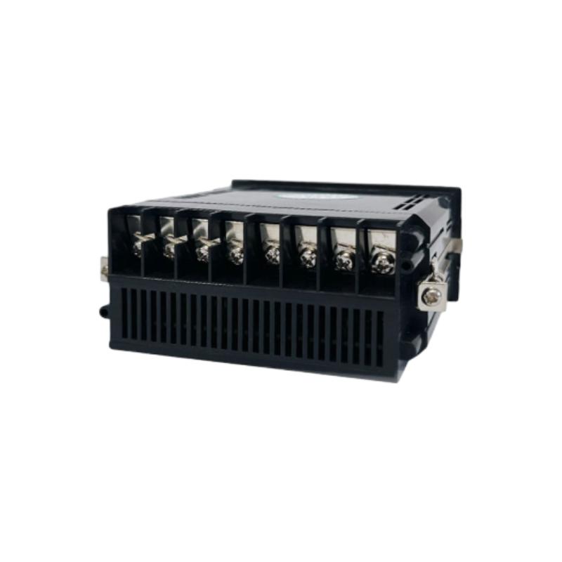
Signal transmission relies entirely on specialized low-loss coaxial cables. Installers route these shielded cables from the sensors to the door. Avoid placing signal wires near high-current power cables to prevent noise. Electromagnetic interference can cause false readings on the front display. We recommend using a 54×32mm Switchgear Voltage Indicator for compact control doors. This specific dimensions model fits neatly into standard panel cutouts. Run the cables through protective plastic conduits to prevent physical shearing. Bending coaxial cables too sharply reduces signal strength significantly. Keep the bend radius within the manufacturer limits during wire routing. Technicians must label each cable phase clearly with permanent markers. Confusing the phases during connection leads to incorrect phase sequence display. Proper terminal crimping prevents signal attenuation and maintains constant readouts. Checking cable continuity before final door mounting prevents troublesome re-work.
Secure the Switchgear Voltage Indicator into the Panel Door
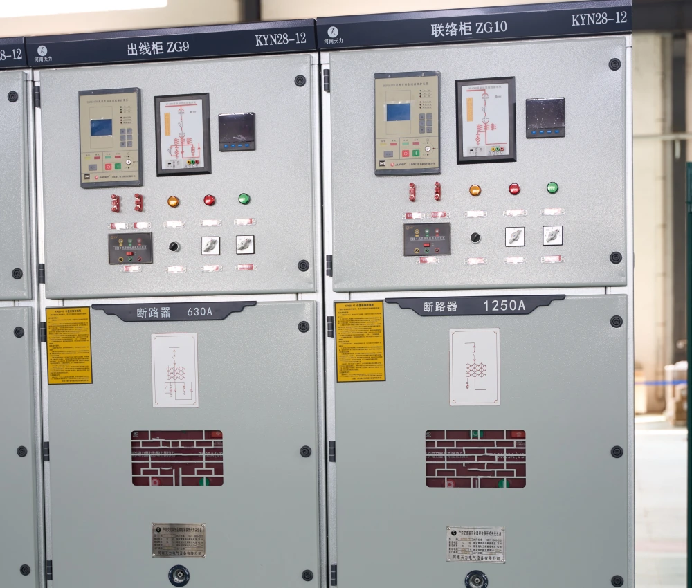
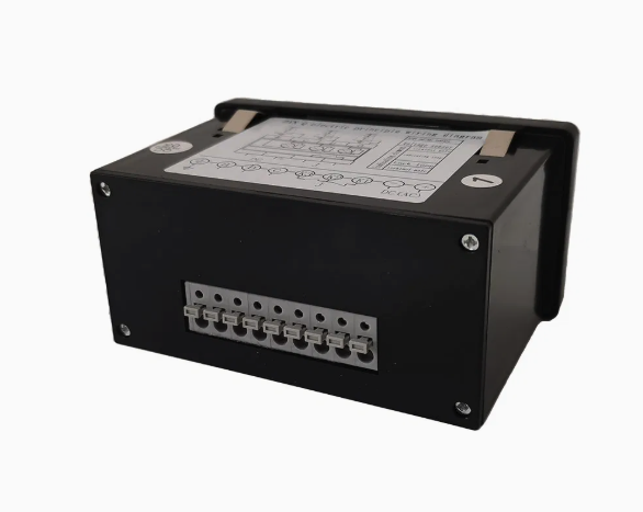
Mounting the display unit requires a precise cutout on the front door. Ensure the gasket seals tightly against the metal surface to block dust. This IP54 protection level remains crucial for industrial environments. Securing brackets must hold the indicator frame firmly in place. Proper alignment ensures that operators can read the display easily. Connection terminals on the back accept the coaxial cable plugs. Slide the plugs until they click into their respective slots. Do not apply excessive force to the sensitive terminals. Cable strain relief ties prevent the weight from pulling on connectors. Technicians must double-check the mechanical stability of the unit now. Vibration from vacuum circuit breakers must not dislodge the housing. Sturdy installations prevent premature display failure caused by operational shocks. Such physical steps transition the project into the testing phase.
Technical Specification Comparison for Voltage Indicators
| Parameter | LRM System Spec | HR System Spec |
|---|---|---|
| Standard Compliance | IEC 61243-5 LRM | IEC 61243-5 HR |
| Threshold Voltage | 4V to 5V (from divider) | 90V to 100V (direct) |
| Input Impedance | 2 Megaohms | 36 Megaohms |
| Indicator Connector | BNC coaxial plug | Single-pole plug |
Interpreting Technical Specifications for Safe Panel Operation
Engineers must evaluate the distinct operational differences between LRM and HR systems. LRM components offer lower impedance and enhanced protection for control circuits. Selecting a suitable voltage module requires careful matching of system parameters. Capacitive voltage dividers must deliver exactly the correct threshold voltage range. Connecting high-impedance devices to low-impedance dividers creates inaccurate phase readings. Operators should verify these specifications prior to final installation of devices. Safety standards like IEC 61243-5 dictate these hardware specifications globally. Using unmatched components will lead to premature electronic component degradation. Testing teams must record all threshold values during pre-commissioning phases. This meticulous approach guarantees proper system operation under high electrical load conditions. Accurate impedance matching minimizes signal distortion and prevents false negative indications. Technical diligence maintains continuous grid reliability and ensures personnel protection.
Installation Clearances and Torque Tolerances
| Component Item | Minimum Clearance | Tightening Torque |
|---|---|---|
| Coupling Electrode | 120 mm from wall | 25 Newton meters |
| Coaxial Grounding | 50 mm from busbars | 9 Newton meters |
| Indicator Housing | 10 mm from metal frame | 2.5 Newton meters |
| Terminal Connectors | 15 mm phase-to-phase | 1.2 Newton meters |
Implementing Proper Physical Clearances for Electrical Safety
Adhering to correct clearances protects the internal electronic circuitry from high-voltage flashovers. Tightening all mechanical connectors with calibrated torque wrenches prevents loose contacts. A loose sensor connection can cause signal interruption or destructive localized heating. Each installed Switchgear Voltage Indicator undergoes mandatory testing before final commissioning. Excessive vibration will slowly loosen screws that lack correct tightening torque. Grounding brackets must connect directly to the main copper earth bar. This low-resistance path safely redirects capacitive leakage currents to ground. Installing insulation barriers provides additional security inside compact medium-voltage compartments. Maintenance schedules must include routine inspections of all cable connections. Ensuring mechanical tightness guarantees the uninterrupted monitoring of system phases. Qualified safety officers must inspect every single mounting point meticulously. Such systematic verification maintains the integrity of the whole electrical installation.
Sequential Commissioning Steps for Voltage Detection Systems
- Phase checking with an auxiliary testing device.
- Verification of insulation resistance of the coaxial lines.
- Measurement of actual capacitive current at the test sockets.
- Visual inspection of the LED activation sequence during powering.
Verifying Threshold Voltages During System Testing
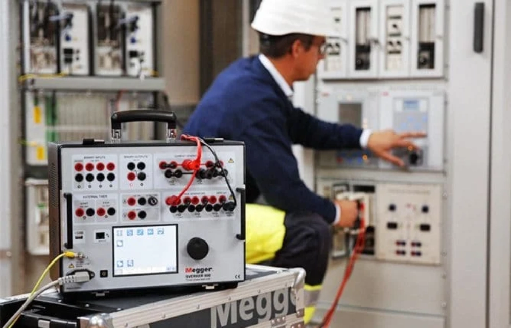
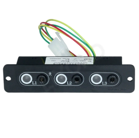
Commissioning starts with measuring the electrical values at the external test sockets. Technicians measure the microampere current using specialized high-impedance measuring instruments. Standard systems must display the active voltage phase clearly without fluctuation. We can install an Inductive High Voltage Indicator Display for primary busbar monitoring. This high-performance display offers reliable optical warnings even during auxiliary power failures. Connecting test devices to the front sockets must not disrupt the primary circuit. Operators rely on these test sockets to perform safe phase comparison checks. Incorrect phase relationships will trigger immediate alarms in the substation control room. Checking phase synchronization prevents catastrophic short circuits during parallel switching operations. Reliable voltage indication remains the cornerstone of safe grid operation. These visual verification methods form the primary layer of personal defense. Such testing routines ensure that the distribution network operates within tolerances.
Troubleshooting Common Signal Issues in Medium Voltage Panels
Field operations sometimes encounter fluctuating or entirely absent signals on the panel. Loose coaxial ground shielding often causes high noise levels in the reading. Testing the resistance between the shield and ground identifies connection problems. Faulty coupling electrodes can also trigger false indications of de-energized phases. Damaged components must undergo immediate replacement to restore safety monitoring capabilities. Technicians should isolate the circuit before replacing any faulty indicator parts. Corrosion on test sockets occasionally prevents accurate phase comparison measurements. Regular cleaning with specialized electrical contact sprays restores full conductivity. Checking the auxiliary power supply clarifies if the LED module failed. This structured diagnostic approach quickly isolates issues without causing unnecessary panel downtime. Experienced substation maintenance crews carry spare indicators to minimize repair times. Systematic proactive replacement strategies maintain high availability of key safety equipment.
Preventative Maintenance and Long-Term Calibration Guidelines
Routine calibration maintains the safety verification system at peak operating performance. Annual testing verifies that the internal capacitors have not degraded. Dust accumulation on terminal blocks requires immediate removal using dry air. Tight electrical connections must withstand normal thermal expansion over many years. A properly installed Switchgear Voltage Indicator prevents catastrophic electrical accidents. Recording all capacitive output values helps predict component failure cycles. Insulation resistance tests must occur during every scheduled substation shutdown. Testing teams must upload all data to the central asset database. This continuous monitoring approach prevents sudden unexpected failures of vital equipment. Asset managers schedule maintenance windows based on historical performance statistics. Consistent physical inspections protect expensive transformer and switchgear investments.
FAQ
What is the primary function of a capacitive voltage divider?
Capacitive voltage dividers scale down high busbar potentials to low measurable levels. These primary sensors couple directly with live conductors inside switchgear compartments. They create safe, low-energy output signals for auxiliary electronic displays. This design eliminates direct physical contact with high voltages. Maintenance personnel can safely check phase statuses without risking arc flash incidents. Modern substations rely on these robust dividers to supply constant electrical data. Such reliable scaling methods ensure the overall integrity of diagnostic equipment. Correct physical installation prevents critical system measurement errors during routine operations. Qualified technicians must verify sensor capacitance ratings during initial plant assembly. This strict safety protocol maintains operational security across the power grid.
How often should you test these panel indicators?
Utility standards require testing of all active display indicators annually. Maintenance crews should verify signal brightness during planned network shutdowns. Testing actual voltage thresholds guarantees that LEDs activate at correct levels. Operators perform these tests using external phase comparators at the test sockets. Dust accumulation or environmental humidity requires more frequent inspection intervals. Coastal or heavily polluted industrial areas need semi-annual verification schedules. Keeping detailed records of all inspection findings helps track potential degradation. This documentation supports preventive asset management and enhances general system reliability. Regular validation prevents costly unplanned distribution network outages during winter peak demands. Safety rules mandate immediate replacement of any dimmed or flickering indicator displays. Such proactive steps protect field technicians working on active power busbars.
Can you swap indicators from different manufacturers?
Interchanging indicators from different brands requires severe technical caution. Different manufacturers design capacitive dividers with specific capacitance values. An unmatched display indicator will show completely wrong phase voltage readings. This mismatch presents extreme danger to maintenance crews who rely on signals. Always consult the exact technical manual before making any hardware substitutions. Technical specifications must align precisely regarding threshold current and input impedance levels. Mixing unmatched components voids official switchgear safety certifications from testing laboratories. Qualified electrical engineers must recalculate system capacitances before approving alternative components. Such thorough verification processes keep modern electrical grids operating safely. Standardizing on one reliable product family simplifies warehouse inventory management. This commercial choice reduces human error during hurried field replacement projects.