
How Does A VDIS Capacitive Sensor Detect Voltage?
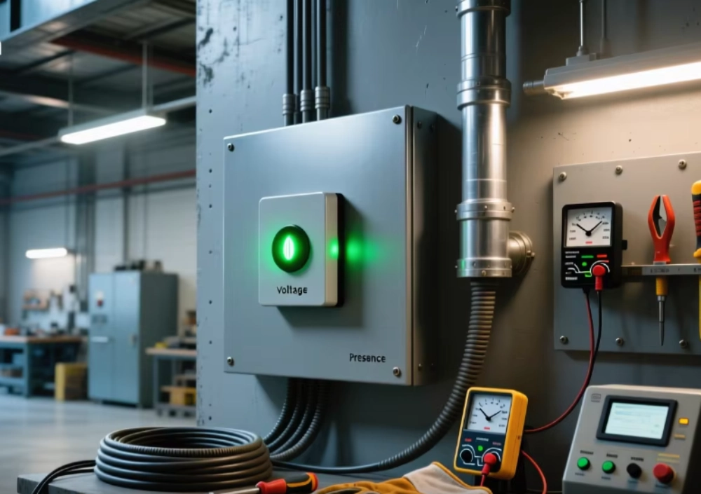
VDIS Capacitive Sensor detects voltage through capacitive coupling and signal processing for reliable MV switchgear voltage indication.
What Is a VDIS Capacitive Sensor?
VDIS Capacitive Sensor technology detects whether operating voltage exists within high-voltage equipment. The sensing structure does not require direct contact with the main conductor. Instead, it uses controlled electrical coupling to obtain a low-energy signal. That signal enters a detection circuit for evaluation. The system then provides a clear voltage presence or absence indication. This approach suits medium-voltage switchgear because it separates the detection interface from the primary circuit. Engineers can integrate sensing elements near busbars, cables, or other energized conductors. Each phase normally requires an independent sensing path. Correct phase allocation therefore becomes essential during installation and commissioning. The system focuses on voltage presence rather than precision electrical measurement. This distinction matters when engineers select detection equipment for switchgear safety and operational monitoring.
How Does a VDIS Capacitive Sensor Detect Voltage?
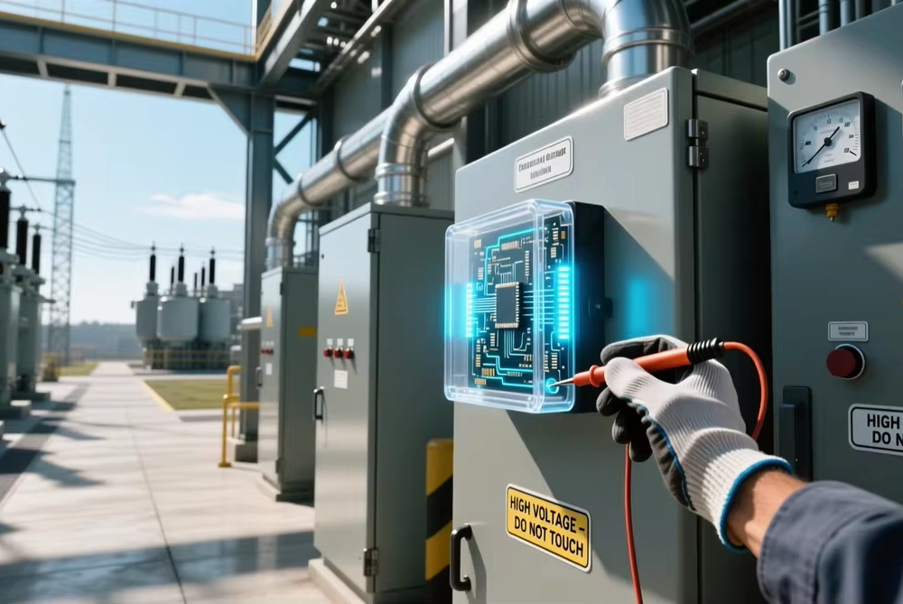
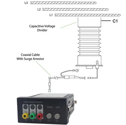
A VDIS Capacitive Sensor detects voltage through capacitive coupling between conductive elements. The energized conductor generates an electric field around the sensing structure. A sensing electrode responds to changes within that electric field. The coupling path transfers a small alternating electrical signal toward the detection circuit. Signal magnitude depends on the designed capacitance between the primary conductor and sensing electrode. The detection circuit evaluates this signal against a defined operating threshold. When the signal reaches the required level, the indicator shows voltage presence. When the signal falls below the relevant condition, the indicator changes state. This process does not directly reproduce the primary voltage value. Instead, it establishes a reliable relationship between the energized conductor and indication circuit. Proper sensor geometry therefore remains important for consistent detection performance.
How Does Capacitive Coupling Create a Detection Signal?
Capacitive coupling depends on an electric field between two conductive structures. The primary conductor acts as one conductive element in the coupling arrangement. The sensing electrode forms another conductive element at a controlled distance. Insulating material separates these structures and prevents direct electrical contact. Alternating voltage creates a changing electric field across this arrangement. That changing field produces displacement current through the effective capacitance. The resulting signal remains much smaller than the primary system voltage. Engineers can then process this signal using a protected detection circuit. Coupling capacitance depends on electrode area, spacing, dielectric properties, and surrounding conductive structures. Stray capacitance can also influence signal behavior during operation. Therefore, mechanical construction directly affects electrical detection characteristics. Stable geometry helps maintain predictable signal levels throughout the intended operating range.
What Components Form the Detection Circuit?
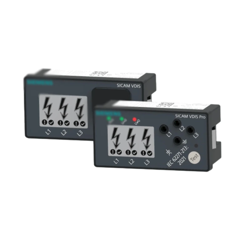
A voltage presence detection system contains several coordinated electrical components. The sensing element first couples with the energized primary conductor. A connecting lead then transfers the signal toward the detection interface. The voltage limiting element controls the accessible signal under specified abnormal conditions. The indicator receives the processed signal and presents the operating state. Testing points can provide a controlled interface for functional verification. Each phase normally contains its own corresponding detection path. This arrangement prevents one phase from determining another phase's indication. IEC 62271-213 defines important requirements for coupling systems and associated VDIS components. The standard also addresses voltage limiting elements, indicators, testing points, and connecting leads. Engineers should evaluate these components as one complete system. Compatibility between individual parts directly affects reliable voltage indication.
Which Electrical Parameters Influence Detection Performance?
Several electrical parameters influence the signal generated by capacitive detection. Rated voltage defines the intended operating range for the switchgear application. System frequency also affects the behavior of alternating electrical signals. Coupling capacitance determines how much signal reaches the detection circuit. Physical spacing influences the effective capacitance between conductive elements. Insulation materials affect electric field distribution around the sensing structure. Detection thresholds determine when the indicator recognizes voltage presence. Engineers should therefore evaluate electrical and mechanical parameters together. A suitable design balances signal strength with insulation requirements. Excessive coupling can create unwanted electrical stress within the detection circuit. Insufficient coupling can produce a signal below the required indication threshold. The following table summarizes several parameters that require attention during system selection.
| Parameter | Function | Possible Effect |
|---|---|---|
| Rated voltage | Defines application range | Incorrect system selection |
| Frequency | Defines AC operating condition | Signal response variation |
| Coupling capacitance | Controls transferred signal | Detection threshold changes |
| Electrode spacing | Influences electric field coupling | Signal variation |
| Insulation structure | Maintains electrical separation | Leakage or insulation stress |
Why Does Installation Geometry Matter?
Installation geometry directly affects capacitive voltage detection because physical dimensions determine electrical coupling. The sensing electrode must maintain its intended position relative to the energized conductor. Changes in distance can modify the effective capacitance within the detection path. Nearby metal structures can also introduce additional stray capacitance. Cable routing may create unintended coupling with adjacent conductors. Insulating barriers can alter electric field distribution around the sensing element. Engineers should therefore follow approved mechanical drawings during installation. Mounting brackets should hold sensing components securely against vibration and thermal movement. The following installation checks can reduce common commissioning problems.
- Confirm the switchgear rated voltage and frequency.
- Verify the sensing position for every phase.
- Check each terminal against the wiring diagram.
- Inspect electrode spacing and mounting alignment.
- Verify insulation clearance around conductive parts.
- Check connecting leads for damage or incorrect routing.
- Confirm the correct indicator channel for each phase.
- Record final installation conditions before energization.
How Can Engineers Verify the Installation?
Engineers should verify the physical installation before applying operating voltage. The VDIS Capacitive Sensor position should match the approved equipment configuration. Each connecting lead should correspond with its assigned phase. Terminal markings should match the wiring diagram and commissioning records. Insulation surfaces should remain clean and free from conductive contamination. Technicians should also inspect mounting hardware for movement or mechanical damage. Functional checks should confirm that each phase produces the expected indication. A phase-by-phase approach makes abnormal results easier to isolate. Test records should document the equipment configuration and observed indication. This information becomes valuable during future maintenance or troubleshooting. Correct installation reduces the possibility of false indication caused by wiring or mechanical errors. It also supports consistent performance across repeated switchgear production batches.
What Happens During a Real Switchgear Application?
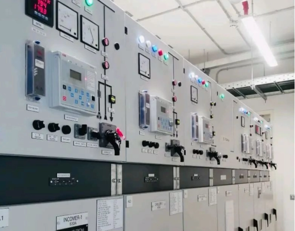
Consider a medium-voltage industrial switchgear lineup serving a manufacturing facility. The equipment uses three separate voltage detection paths for its three primary phases. A DXN8D 12 voltage presence indicating system can provide a practical indication interface for this type of application. During commissioning, technicians energize the primary circuit under controlled operating procedures. The front indicator should then display the expected status for each phase. Suppose one phase remains dark while the other two phases indicate voltage. Technicians first compare the physical connection with the approved wiring schedule. They then inspect the associated coupling interface and connecting lead. If the electrical connection remains correct, they check the sensor position. A shifted sensing element can change the intended coupling relationship. After correcting the installation, technicians repeat the phase-specific functional test. This scenario reflects a realistic commissioning issue in compact medium-voltage switchgear. It demonstrates why electrical checks and mechanical inspection must work together.
How Does Phase Identification Affect Voltage Indication?
Phase identification determines whether the displayed status represents the correct primary conductor. Each sensing path must correspond with its designated phase. A crossed connection can produce an apparently normal indication on the wrong channel. Such an error can remain unnoticed when technicians only check whether indicators illuminate. Commissioning should therefore verify both indication and phase identity. Engineers can compare terminal numbers, cable markings, and physical conductor positions. They should also verify the phase sequence against the approved switchgear documentation. This process becomes especially important when several detection interfaces occupy a compact panel. Clear terminal identification reduces installation errors during manufacturing and field assembly. Consistent phase labeling also simplifies future maintenance. A correct phase map provides a reliable connection between the primary circuit and displayed voltage state.
How Do Environmental Conditions Affect Capacitive Detection?
Environmental conditions can influence insulation and signal stability inside switchgear. High humidity can increase surface leakage across contaminated insulating materials. Condensation creates additional electrical paths across surfaces that should normally remain highly resistive. Temperature changes can also affect electronic detection components and mechanical interfaces. Outdoor installations typically experience wider temperature and humidity variations. Industrial locations may introduce dust, chemical contamination, or conductive particles. Enclosure design can reduce exposure when its protection level suits the installation environment. Engineers should evaluate condensation risk alongside temperature and humidity limits. Regular inspection can identify contamination before it creates electrical problems. Environmental conditions should also form part of commissioning records for demanding installations. Proper enclosure selection and insulation maintenance help preserve the intended electrical behavior over time.
What Role Does the Voltage Limiting Element Play?
The voltage limiting element provides an important protection function within the detection path. It restricts the voltage available at designated accessible connection points. This function becomes important because the detection system connects electrically to a high-voltage primary circuit. The limiting element therefore helps control the secondary-side electrical conditions. Its characteristics must match the complete coupling system and intended application. Engineers should not treat the limiting element as an independent accessory. Its performance depends on the surrounding sensing and detection architecture. The following table shows how several system elements contribute to overall operation.
| System Element | Primary Function | Engineering Concern |
|---|---|---|
| Coupling system | Transfers a controlled signal | Capacitance and insulation |
| Voltage limiting element | Restricts accessible voltage | Protection coordination |
| Indicator | Displays voltage status | Threshold and visibility |
| Testing point | Supports functional verification | Accessibility and safety |
| Connecting lead | Transfers the detection signal | Phase identification |
Why Is Commissioning Important for Long-Term Reliability?
Commissioning confirms that the installed detection system matches its intended electrical configuration. Technicians should verify every phase independently before equipment enters routine service. The inspection should cover wiring, sensor position, insulation, indicator response, and testing interfaces. Any abnormal indication requires investigation before final acceptance. Engineers should record test conditions because future troubleshooting depends on reliable baseline information. Maintenance teams can compare later results against those original records. This approach helps identify gradual changes caused by contamination, mechanical movement, or component aging. Commissioning also confirms that the switchgear configuration matches approved technical documentation. For customized systems, documentation should include sensor specifications and interface details. A complete record reduces uncertainty when replacement components become necessary. Reliable commissioning therefore supports both immediate operational safety and future maintenance efficiency.
How Can OEM Projects Adapt Capacitive Detection?
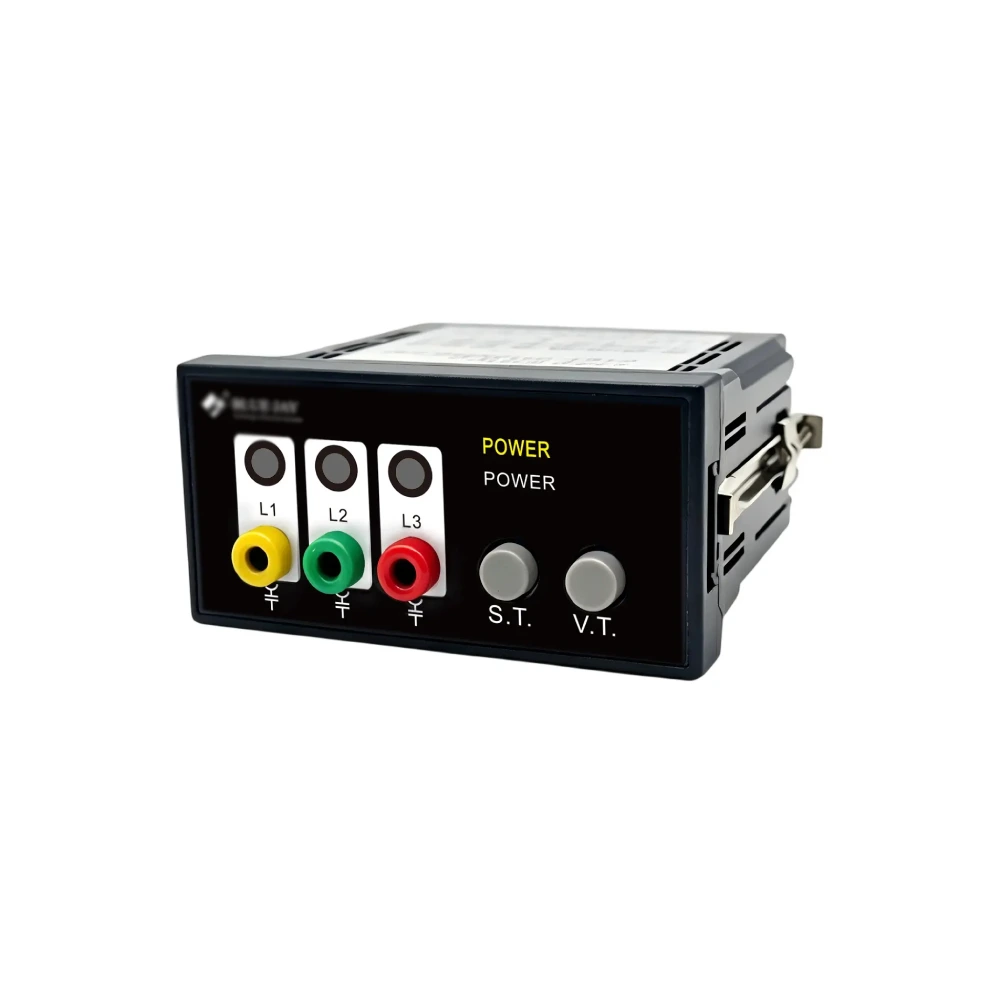
OEM projects often require electrical and mechanical customization for different switchgear platforms. Panel dimensions can vary between equipment families and installation arrangements. Detection interfaces may also require different terminal positions or connecting lead lengths. An 88x28mm switchgear voltage indicator VPIS OEM/ODM project may require close coordination between sensing and indication components. Mechanical fit must match the switchgear panel cutout and internal installation space. Electrical compatibility also requires careful review of rated voltage and detection thresholds. Engineers should verify these parameters before selecting a replacement or customized assembly. Interface design should preserve phase identification throughout the complete detection circuit. Testing points also need appropriate accessibility and electrical protection. IEC 62271-213 specifies a voltage limiting element within each phase system. This element helps control voltage at accessible testing or connecting points under defined failure conditions.
What Should Engineers Check Before Final Acceptance?
Final acceptance should confirm both electrical performance and mechanical conformity. Engineers should compare the finished assembly against approved drawings and technical specifications. Every phase should produce the correct indication under controlled test conditions. The VDIS Capacitive Sensor terminal identification should match the documented phase arrangement. Sensor mounting should remain secure after installation and inspection. Insulation surfaces should show no visible contamination or damage. Connecting leads should follow the intended routing without unnecessary proximity to unrelated circuits. Testing points should remain accessible where the design requires them. Environmental conditions should also remain within the specified operating range. The final records should include inspection results and any corrective actions. This documentation creates a traceable baseline for future service activities. A disciplined acceptance process helps prevent small installation errors from becoming operational problems.
FAQ
Can Capacitive Voltage Detection Measure Exact Primary Voltage?
Capacitive voltage detection normally focuses on voltage presence rather than precision measurement. The sensing circuit receives a controlled signal from the energized primary conductor. Detection electronics then compare that signal with predefined operating conditions. The resulting indication shows whether the required voltage state exists. This process differs from metering applications that require defined measurement accuracy. Engineers should therefore avoid using a presence indicator as a substitute for a precision voltage instrument. Equipment documentation should clearly define the intended function of each detection interface. When precise voltage values are required, a dedicated measurement system should provide the necessary accuracy. Safety procedures should also remain independent from the indicator status.
What Causes Incorrect Voltage Presence Indication?
Incorrect indication can originate from electrical, mechanical, or environmental conditions. Wiring errors can assign one phase signal to another indicator channel. Poor coupling can reduce the signal below the required detection threshold. Sensor displacement can change the intended capacitance between conductive structures. Contamination may increase leakage across insulating surfaces. Condensation can create similar problems under humid conditions. Engineers should begin troubleshooting with rated voltage and phase assignments. They should then inspect terminals, connecting leads, sensor position, and insulation. Functional testing should verify each phase separately after corrective work. This systematic approach helps identify the actual fault instead of replacing components unnecessarily. Proper commissioning records can further shorten troubleshooting time during future service.
Where Is Capacitive Voltage Detection Normally Installed?
Capacitive voltage detection is normally integrated into the voltage sensing path of medium-voltage switchgear. The sensing structure sits near an energized conductor or within a designed coupling interface. Its exact position depends on the switchgear construction and insulation arrangement. Some systems integrate sensing components directly into the primary equipment. Other systems use separable interfaces that connect with external indication units. Mechanical placement must preserve the intended coupling characteristics and insulation distances. Connecting leads must also maintain correct phase identification throughout the circuit. Testing interfaces may provide access for functional verification during commissioning. Engineers should always follow the equipment drawings for exact mounting locations. The selected position should also support inspection and maintenance without compromising electrical safety.