How Does A VPIS Indicator Work In Electrical Systems?
A VPIS Indicator ensures operator safety in medium voltage switchgear by providing real-time visual voltage presence detection.
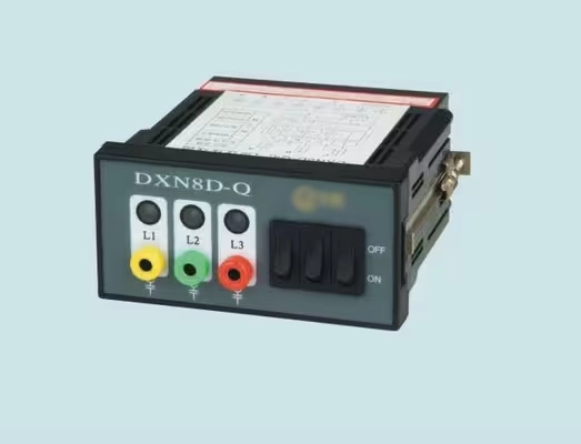
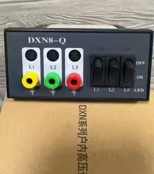
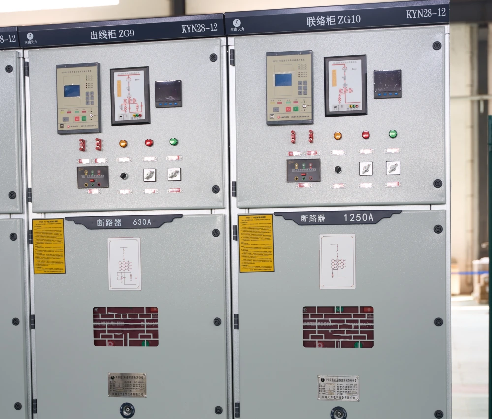
Medium voltage switchgear panels protect critical power grids. Operators require reliable safety mechanisms during daily electrical maintenance routines. A standard VPIS Indicator provides immediate visual confirmation of voltage presence. This unit connects directly to the system capacitive dividers. It detects active high voltage states without direct physical contact with live conductors. Engineers rely on these devices to prevent catastrophic switching errors. High voltage environments present serious risks to field technicians. Visual signaling reduces these dangers significantly. Technicians observe the bright flashing signals on the front panel. Consequently, maintenance teams perform their tasks with high confidence. Safety standards mandate such visual verification tools in modern substations. Reliable grid performance depends heavily on continuous monitoring devices.
Physical Principles of a VPIS Indicator
Capacitive coupling forms the operational basis of voltage detection. High voltage conductors contain a built-in coupling electrode. This electrode creates a small capacitor with the high voltage conductor. Another capacitor exists between the coupling electrode and the earth ground. Together, these two elements establish a capacitive voltage divider circuit. The circuit reduces the dangerous primary voltage to a safe level. Low voltage signals travel safely to the indicator display panel. These signals measure only a few volts during normal operation. Passive electrical energy powers the display without external auxiliary sources. Solid-state circuitry inside the unit processes the incoming current. Finally, the system flashes to indicate a live high voltage busbar. This physical process supports continuous operation during complete control power blackouts.
Designing a Reliable VPIS Indicator System
Engineering robust safety devices requires careful component selection. Liquid crystal displays or light emitting diodes serve as the primary visual outputs. Manufacturers select high-brightness light sources for optimal visibility in dark substations. The internal circuitry contains overvoltage protection components to absorb sudden electrical surges. Flame retardant polycarbonate materials form the external housing of the device. This housing protects sensitive electronics from dust, moisture, and mechanical impacts. Connection leads utilize heavy shielding to prevent electromagnetic interference from nearby busbars. Sealed input terminals prevent accidental contact with incoming signal wires during inspection. Every component must withstand extreme temperature fluctuations inside the switchgear enclosure. Consequently, the device maintains operational integrity for decades without maintenance.
Compliance Standards and Threshold Voltages
International electrotechnical commissions enforce strict manufacturing guidelines for power distribution components. The IEC 62271-206 standard governs these testing procedures. This standard defines clear voltage threshold limits for visual indications. Safe operation dictates that the device must not flash at low voltages. Specifically, the VPIS Indicator remains dark below ten percent of the nominal line voltage. Such limits prevent false positive readings from residual electromagnetic fields. Conversely, the device must flash reliably once voltage exceeds forty-five percent. Testing laboratories subject these units to severe dielectric tests.
Engineers verify impulse voltage withstand capabilities to ensure complete field reliability. Compliance with international standards guarantees compatibility with global utility grids. This rigorous testing minimizes unexpected equipment failures.
Installation Practices in Medium Voltage Cubicles
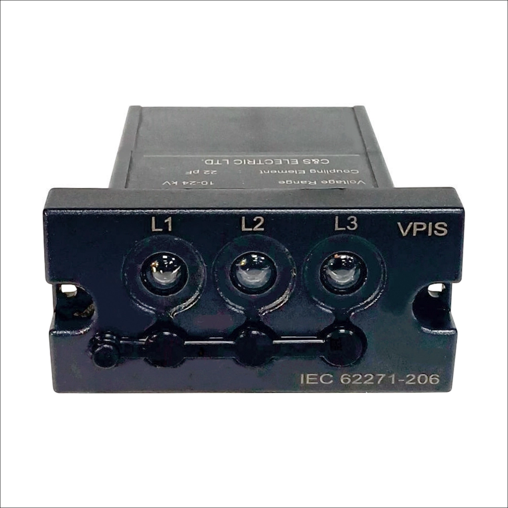
Proper physical integration within the switchgear housing ensures safety. Technicians mount the visual module on the low voltage compartment door. This position provides maximum visibility for substation operators walking the floor. Panel builders often select the compact 54×32mm Switchgear Voltage Indicator for space-constrained installations. Such compact dimensions fit easily into modern high-density switchboard configurations. Connecting wires must follow specific routing paths to avoid high-voltage electric fields. Installers secure the ground terminal of the module to the main copper earth bar. A solid ground connection prevents dangerous static charge accumulation on the front bezel. Commissioning teams perform initial insulation tests before energizing the main busbars. These tests confirm the integrity of the capacitive divider insulation. Careful installation protects both operators and electronic components.
Comparison of High Voltage Signaling Technologies
| Technology Type | Input Impedance | Power Source | Primary Standard |
|---|---|---|---|
| Visual VPIS | Very High Impedance | Self-Powered (Capacitive) | IEC 62271-206 |
| Voltage Detection System (VDS) | Calibrated Impedance | Self-Powered (Capacitive) | IEC 61243-5 |
| Neon Indicator Lamp | Low Impedance | Direct AC Line Power | Legacy Standards |
Technical Details of Voltage Detection Systems
The performance matrix highlights critical differences between active and passive signaling units. Passive liquid crystal displays offer superior reliability over older filament bulbs. These older technologies burn out quickly and require frequent physical replacement. Modern electronic circuits operate continuously for over fifteen years. High input impedance ensures that leakage currents remain well within safe limits. This prevents electric shock hazards for operators testing the front panel interfaces. Measuring points on the front bezel allow phase comparison tests without opening switchgear doors. Such functionality reduces substation maintenance time during commissioning phases. Engineers analyze these specific parameters to select the safest monitoring options. Operational safety increases when teams can verify voltage presence externally.
Comparative Selection of Voltage Indicators
| Electrical Property | Standard Value | Safety Margin |
|---|---|---|
| Non-Indication Threshold | Below 10% of Un | Prevents crosstalk false positives |
| Full Indication Threshold | Above 45% of Un | Guarantees live busbar warning |
| Dielectric Withstand Voltage | 2 kV for 1 minute | Protects auxiliary low voltage line |
Analyzing Threshold Performance Parameters
Electrical thresholds determine whether a visual system complies with global utilities standards. The VPIS Indicator requires precise calibration to avoid false signaling from adjacent phase crosstalk. High-voltage installations create strong electromagnetic fields that can induce phantom currents in idle cables. Internal filtration circuits must suppress these weak signals effectively. Consequently, the display only activates when the primary line carries real operating voltage. This design ensures that operators do not make decisions based on inaccurate visual data. Laboratory testing confirms that the threshold voltages remain stable over decades. Insulation resistance values between primary poles and low voltage terminals exceed limits. Such isolation ensures that the low voltage front panel remains entirely safe during severe grid faults.
Routine Maintenance and Phase Comparison
- Perform visual inspection of the housing unit before testing.
- Connect the standard phase comparator to the front testing points.
- Measure the output current at each phase terminal separately.
- Document any deviations in light flashing intensities across phases.
Operational Execution of Phase Testing
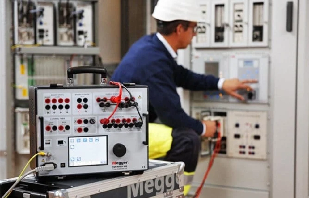
Maintenance procedures require strict adherence to standardized electrical safety guidelines. Operators use specialized phase comparators directly on the front panel testing ports. This phase verification ensures correct connections before closing cross-tie circuit breakers. Technicians often compare the performance with an Inductive High Voltage Indicator Display during dual-source commissioning. These dual checks prevent catastrophic short circuit faults across different substation phases. Regular testing also checks the health of the internal light emitting diodes. A faulty indicator can lead to incorrect assumptions about busbar dead states. Consequently, annual testing routines form a core part of substation asset management. Safe working practices demand multiple independent confirmations before grounding live cables. Such operational discipline minimizes risk during emergency power restoration procedures.
Future Trends in Smart Switchgear Monitoring
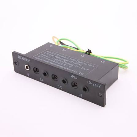
Smart grids require advanced digital interfaces for remote substation automation systems. Modern power networks integrate secondary signal contacts into the visual monitoring block. This setup transmits real-time voltage status directly to centralized SCADA control rooms. Consequently, operators monitor switchgear health without entering dangerous substation zones. The classic visual indicator now evolves to feature smart auxiliary communication ports. These electronic upgrades allow continuous remote monitoring of vital grid nodes. Reliability increases while reducing the need for manual on-site panel inspections. Future designs will incorporate self-diagnostic features to report internal component failure. Digital infrastructure depends heavily on these robust visual and digital interfaces. Operational safety remains the ultimate objective for modern power distribution system designers.