
How Is A VDIS Installed In Switchgear?
VDIS Installation Requirements cover mounting, wiring, insulation, phase detection, testing, and safe switchgear integration.
VDIS Installation Requirements For Switchgear Preparation
VDIS Installation Requirements begin with accurate switchgear information and installation planning. Engineers first confirm the cabinet voltage class, frequency, phase arrangement, and available space. The installation area should provide clear access for inspection and maintenance. Panel-mounted displays also need suitable visibility from the normal operating position. Internal components must not interfere with doors, barriers, busbars, or cable compartments. Installation drawings should identify every interface before physical work begins. The engineering team should compare the approved drawings with the actual cabinet structure. Any dimensional difference should receive technical approval before drilling or modification. This approach reduces installation errors and prevents unnecessary cabinet rework. Proper preparation also creates a clear basis for electrical testing after installation.
How Should The Switchgear Be Prepared Before Installation?
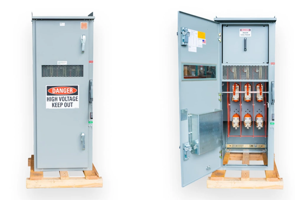
Switchgear preparation involves mechanical, electrical, and environmental checks. The cabinet should have a stable mounting surface for the display unit. Panel thickness must match the selected fixing method and hardware. Engineers should also verify door movement before selecting the final display position. A poorly positioned unit may become difficult to inspect during routine operation. Internal wiring routes require sufficient separation from high-voltage conductors. Terminal blocks should remain accessible without disturbing unrelated circuits. Cable entry points should also prevent excessive bending or mechanical stress. The enclosure should remain properly sealed after installation. Any unused opening needs suitable protection against dust and moisture. These details matter because VDIS equipment operates within a larger electrical assembly. A successful installation therefore depends on cabinet integration rather than component mounting alone.
What Electrical Parameters Must Be Confirmed First?
VDIS Installation Requirements include accurate verification of switchgear electrical parameters before connection. Engineers should confirm the cabinet rated voltage and system frequency against equipment specifications. Phase identification must remain consistent throughout the complete detection circuit. Each phase connection should correspond with its designated terminal and coupling interface. Incorrect phase assignment can create misleading indication conditions. The team should confirm the intended voltage detection arrangement before wiring begins. Some switchgear designs use dedicated interfaces for each phase. Other configurations may integrate detection components with specific internal conductors. Control circuits require separate attention because their voltage differs from the primary circuit. AC and DC auxiliary supplies should never be treated as equivalent without verification. Careful parameter matching creates a reliable foundation for later functional testing.
How Are Voltage Detection Interfaces Connected?
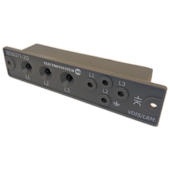
Voltage detection interfaces transfer electrical information from the primary circuit toward the indication system. Each phase requires the correct connection path through its designated interface. Engineers should follow the approved wiring diagram rather than relying on physical proximity. Terminal numbers must match both the cabinet drawing and component markings. Phase identification should remain consistent from the primary coupling point to the display. Loose terminals can create unstable signals and intermittent indication. Excessive conductor length may also complicate cabinet routing and maintenance. The installation team should secure conductors against vibration and accidental movement. Sharp bends should be avoided around terminals and connection points. After wiring, technicians should verify continuity and phase correspondence before energization. These checks help prevent incorrect indication caused by wiring mistakes.
What Insulation And Clearance Conditions Matter?
Insulation coordination becomes critical when indication components operate near medium-voltage circuits. Engineers should evaluate electrical clearance around terminals, conductors, and nearby grounded structures. Creepage distance also matters when surfaces may collect dust or moisture. Cabinet contamination can reduce surface insulation performance over time. Condensation creates additional concern because moisture can form conductive paths across insulating surfaces. Installation positions should therefore maintain suitable separation from exposed high-voltage components. Barriers can provide additional protection where physical separation remains limited. Sharp conductive edges should not approach insulation surfaces unnecessarily. Cable insulation must also match the electrical and environmental conditions. The final arrangement should preserve the intended dielectric performance of the switchgear. These considerations support safer operation and reduce the risk of insulation-related faults.
What Mechanical Details Matter During VDIS Installation?
Mechanical installation requires accurate dimensions and stable fixing. The panel opening should match the specified display dimensions without excessive clearance. Oversized openings can weaken the panel and complicate enclosure sealing. Undersized openings may place mechanical stress on the display housing. Fixing hardware should hold the unit securely during door movement and cabinet vibration. The display position should also provide an unobstructed viewing angle for operators. A practical installation keeps the indication area visible without requiring unsafe movement. Engineers should check nearby handles, locks, labels, and control devices before final fixing. For example, a 88x28mm switchgear voltage indicator vpis OEM/ODM configuration may require specific panel dimensions. Such dimensions should match the approved mechanical drawing before fabrication. Accurate mounting reduces later alignment problems and supports consistent cabinet production.
What Wiring Practices Improve Installation Reliability?
VDIS Installation Requirements also cover wiring practices that support signal stability and maintenance efficiency. Engineers should separate indication wiring from circuits that can create electrical interference. Conductors should follow organized routes with secure fixing points. Terminal connections need sufficient tightening without damaging the conductor or terminal body. Each wire should carry a clear identification that matches the approved schematic. Excess conductor length should remain controlled rather than forming large unsupported loops. Routing should also preserve access to terminals and inspection points. Where cabinet construction requires crossing different circuit groups, the routing should maintain suitable separation. Technicians should inspect cable insulation after pulling and terminating every conductor. Damaged insulation can create risks that remain hidden during visual operation. A disciplined wiring method makes later troubleshooting faster and reduces accidental disconnection during maintenance.
VDIS Installation Requirements Checklist For Site Work
A structured checklist helps technicians verify installation conditions before energizing the switchgear. The checklist should cover both physical installation and electrical configuration. It should also include environmental factors that may affect long-term operation. Each item should receive a clear inspection result and responsible confirmation. Engineers can use the following points during factory assembly or field commissioning:
- Confirm switchgear rated voltage and system frequency.
- Verify the required phase detection arrangement.
- Check every voltage detection coupling interface.
- Confirm terminal identification and wiring routes.
- Verify electrical clearance and creepage distances.
- Check panel dimensions and mounting positions.
- Inspect cable insulation and conductor condition.
- Verify operating temperature and humidity limits.
- Check enclosure sealing and environmental protection.
- Record functional testing and commissioning results.
How Should The Installation Checklist Be Verified?
The checklist becomes useful only when technicians verify each item against approved documentation. Engineers should compare equipment labels with the latest electrical drawings. Mechanical dimensions should match the production drawing before final cabinet closure. Wiring checks should confirm both terminal identity and phase correspondence. Environmental checks should consider the actual installation location rather than laboratory conditions. Any discrepancy should receive a documented resolution before energization. Factory acceptance testing can provide an additional opportunity to identify wiring or mounting errors. Field teams should repeat critical checks after transportation because vibration can affect terminals and mounting hardware. The final inspection should also confirm that labels remain readable after installation. A documented verification process creates traceability for future maintenance. It also helps separate installation problems from later operational issues.
What Environmental Conditions Affect Installation Reliability?
Temperature and humidity can influence switchgear indication performance and insulation reliability. Indoor cabinets may experience significant temperature changes during seasonal operation. Outdoor installations can face wider temperature swings and higher moisture exposure. Condensation deserves special attention because it can occur when cabinet surfaces cool below the dew point. Poor ventilation can also create localized heat around electronic components. Engineers should check the specified operating temperature range before selecting the installation position. Humidity limits should receive similar attention in coastal or high-moisture environments. Dust and industrial contamination can further increase surface leakage risks. Enclosure protection should therefore match the actual site conditions. The cabinet design should prevent direct water entry while allowing appropriate thermal management. Environmental assessment helps maintain stable indication and electrical insulation throughout service life.
How Is VDIS Tested After Physical Installation?
Testing should begin only after technicians complete mechanical and wiring inspections. The first stage should confirm secure mounting and correct terminal identification. Continuity checks can verify that conductors follow the intended electrical paths. Phase correspondence should then receive careful verification before applying operating voltage. Functional checks should confirm that the indication system responds to the intended electrical condition. Test equipment must match the voltage class and approved commissioning procedure. Technicians should also record abnormal indications rather than resetting them without investigation. A DXN8D 12 voltage presence indicating system may require configuration-specific verification before commissioning. Test records should include equipment identification, measured conditions, and inspection results. Engineers should compare these results with approved acceptance criteria. Proper commissioning confirms both installation quality and functional performance before service.
What Does A Real Switchgear Installation Case Show?
A practical medium-voltage switchgear project illustrates why installation details matter. During one cabinet integration project, the original panel layout left limited space around the indication display. The engineering team moved the display slightly to improve visibility and maintenance access. They also revised the internal wiring route to separate indication conductors from power conductors. Terminal labels were updated to match the revised schematic. During commissioning, technicians discovered an incorrect phase identification on one connection. The team corrected the terminal assignment before applying normal operating voltage. A second verification then confirmed correct phase correspondence and stable indication. This case shows that installation problems often involve several connected details. Mechanical layout, wiring identification, and electrical verification must therefore work together. Early inspection prevented a cabinet modification after final assembly.
VDIS Installation Requirements For Commissioning And Handover
VDIS Installation Requirements should remain part of the final commissioning record. The handover package should contain approved drawings, wiring information, test results, and equipment specifications. Engineers should record the actual cabinet configuration rather than relying only on standard project documentation. Any approved design modification should appear in the final drawing set. Test records should identify the inspection date, equipment reference, and responsible personnel. Maintenance teams need accurate terminal information for future troubleshooting. Mechanical details should also remain available when replacement or panel modification becomes necessary. Environmental conditions should appear in the project documentation when they affect equipment selection. Final records provide valuable evidence during later inspections or fault investigations. A complete handover process therefore protects both operational reliability and maintenance efficiency. Clear documentation also reduces uncertainty when similar cabinets enter future production.
How Can Installation Quality Be Improved During Production?
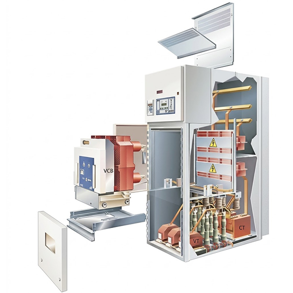
Production teams can improve installation quality by standardizing repeatable inspection points. Mechanical templates can reduce panel opening errors during cabinet fabrication. Wiring labels can follow one approved identification convention across the project. Inspection checkpoints should occur before cabinet closure and before factory testing. Engineers can also photograph critical internal connections for production records. Quality teams should compare completed cabinets against approved drawings rather than informal references. Any deviation should receive technical review before shipment. Supplier documentation should identify electrical and mechanical limits clearly. Replacement components should match the original interface and installation configuration. These controls become especially valuable when multiple cabinets share the same design. Consistent production practices reduce variation and simplify commissioning at the installation site.
FAQ
What Is The Most Important Requirement For VDIS Installation?
The most important requirement is correct electrical and mechanical compatibility. Engineers should first confirm the switchgear voltage and detection arrangement. Phase connections must match the approved circuit diagram. Mechanical dimensions must also fit the selected panel position. Insulation clearance requires attention because detection components operate near electrical circuits. Environmental limits should match the cabinet installation location. Wiring must remain secure, clearly identified, and properly separated from unrelated circuits. Functional testing should follow mechanical and electrical inspections. Technicians should document every critical verification before energization. This approach reduces incorrect indication, wiring faults, and unnecessary commissioning delays. It also creates reliable records for future maintenance and troubleshooting.
Can VDIS Be Installed In Any Switchgear Cabinet?
VDIS cannot automatically fit every switchgear cabinet. Compatibility depends on electrical ratings, mechanical dimensions, detection interfaces, insulation conditions, and environmental limits. The cabinet must provide a suitable mounting position and adequate viewing access. Voltage detection interfaces must also match the intended primary circuit arrangement. Internal clearances should remain appropriate after installation. Wiring routes must avoid conflicts with busbars, barriers, and other electrical circuits. Cabinet doors should operate freely without contacting the installed display. Engineers should also verify temperature and humidity limits for the actual site. A suitable installation requires more than physical space alone. Electrical, mechanical, and environmental parameters must work together. Project drawings and equipment specifications should confirm these conditions before fabrication or field modification.
What Should Be Checked Before Energizing A VDIS?
Technicians should complete mechanical, electrical, and functional checks before energization. Mechanical inspection should confirm secure mounting and correct panel alignment. Electrical checks should verify terminal identification, phase correspondence, and wiring continuity. Insulation and clearance should also match the approved installation requirements. Technicians should inspect conductors for damaged insulation or loose terminals. The testing procedure should use equipment suitable for the applicable voltage class. Functional verification should confirm that the indication responds correctly to the intended voltage condition. Environmental conditions should remain within the specified operating range. Any abnormal indication should trigger investigation before normal energization. Finally, engineers should record test results and approved deviations. Complete pre-energization verification reduces avoidable commissioning risks and supports dependable switchgear operation.