
How Should A VDIS System Be Maintained?
VDIS maintenance covers inspections, functional checks, and fault diagnosis to ensure reliable voltage indication in MV switchgear.
Why Does Regular VDIS Maintenance Matter?
VDIS maintenance helps keep voltage indication equipment reliable in medium-voltage switchgear. A Voltage Detecting and Indicating System uses sensing components and display units to indicate voltage presence. Technicians must monitor sensor condition, electrical connections, indicator performance, and environmental factors. A faulty display can create uncertainty during maintenance or switching operations. Regular inspections help identify deterioration before it develops into a more serious equipment issue. However, a functioning indicator does not replace approved procedures for verifying electrical isolation. Maintenance teams should follow manufacturer instructions and applicable safety requirements. Consistent maintenance also creates records that support fault diagnosis and future inspection decisions.
Which Components Require Routine Inspection?
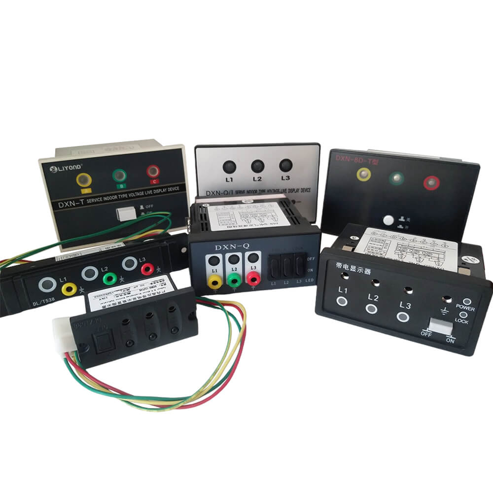
A typical voltage indication arrangement includes capacitive sensors, indicator units, connecting cables, terminals, and mounting interfaces. Each component serves a different role and can develop distinct problems over time. Sensors may suffer surface contamination or insulation damage. Display units can experience illumination failures, damaged housings, or loose connections. Cable insulation may deteriorate under heat, vibration, or unsuitable routing conditions. Terminals can loosen through mechanical stress or poor installation practices. Technicians should inspect accessible components without disturbing energized equipment or sealed assemblies. They should compare installed components against approved drawings and equipment documentation. This approach helps identify physical defects and configuration discrepancies before authorized functional checks.
How Should Technicians Inspect VDIS Sensors?
Capacitive sensors require careful inspection because their condition affects voltage detection performance. Technicians should check accessible insulation surfaces for cracks, contamination, discoloration, and signs of moisture. They should examine mounting points for movement, damaged fasteners, and visible mechanical stress. Sensor connections must match approved drawings and manufacturer specifications. Incorrect connections or unsuitable replacement parts can compromise indication performance. Inspection should also consider nearby conductors, enclosure clearances, and evidence of abnormal heating. Personnel must not touch exposed electrical components or dismantle assemblies without authorization. If inspection reveals suspected insulation damage, the responsible engineer should assess the equipment before returning it to service. Any cleaning method must suit the sensor materials and manufacturer's requirements.
How Can Indicator Display Problems Be Identified?
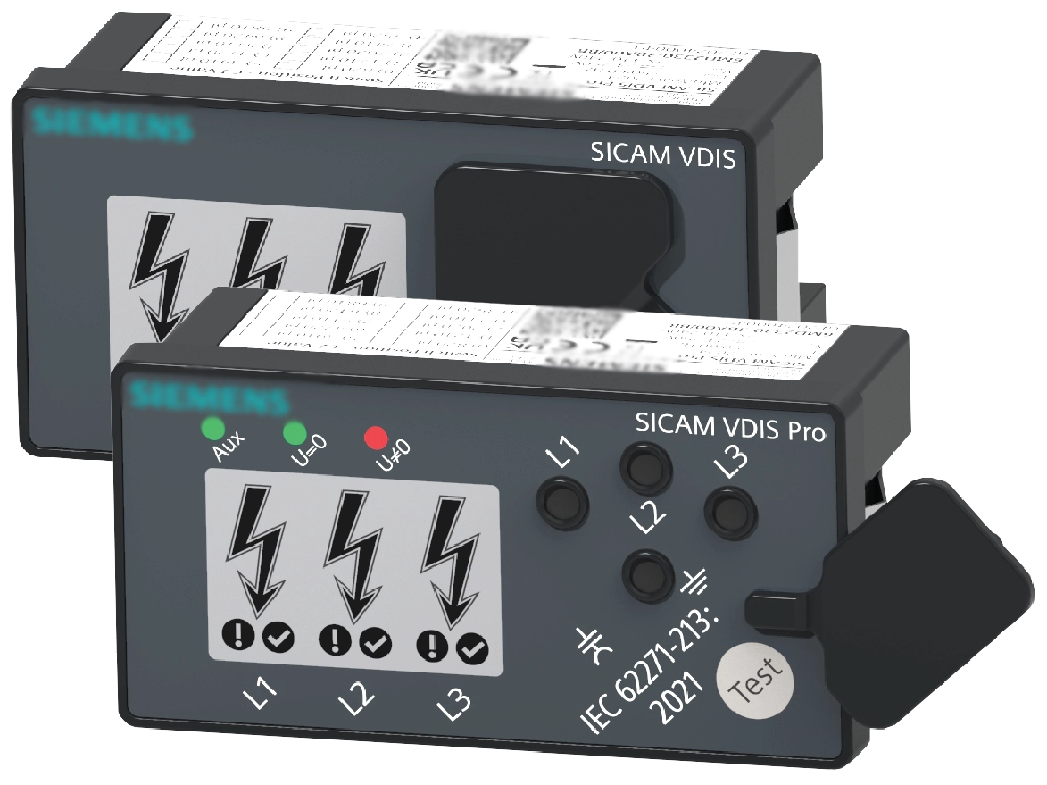
Indicator faults may appear as missing lights, inconsistent phase indications, flickering displays, or unexpected brightness changes. Technicians should record each symptom and compare it with normal operating behavior. A 92×44mm LCD High Voltage Indicator Display may require checks for damaged housing, loose connections, or inconsistent readings. They should check accessible wiring, connectors, mounting conditions, and display housings under approved safety procedures. A dark indicator does not necessarily prove that voltage is absent. Likewise, an illuminated indicator requires interpretation according to the equipment design. Some systems provide interfaces for phase comparison or external testing devices. Personnel should use only compatible test equipment and approved procedures. They must not assume every display fault originates in the indicator itself. Sensor defects, wiring problems, and incorrect component selection can produce similar symptoms.
What Functional Checks Should Maintenance Include?
Functional checks should confirm that the installed system responds according to its specified design. The maintenance team should review the manufacturer's test procedure before selecting a suitable test device. Depending on the system, checks may cover indicator response, phase identification, connecting interfaces, and approved test points. Technicians should verify that test equipment matches the indicator's intended application. They should record equipment identification, test conditions, results, and irregular behavior. A failed check requires further investigation rather than an assumption about the specific defect. Personnel must never improvise electrical stimulation or bypass protective arrangements. After repairs, qualified staff should repeat relevant checks and document satisfactory results before approving normal operation.
How Should VDIS Maintenance Be Performed Safely?
Safe VDIS maintenance begins with an approved work plan and clearly defined equipment boundaries. Authorized personnel should identify the relevant switchgear, isolate applicable energy sources, and prevent unintended re-energization. They must follow site lockout procedures and verify the electrical condition with an approved voltage detector. Required earthing, protective equipment, and access controls depend on the installation and local safety rules. An indicator alone cannot establish that equipment is safe to touch. Technicians must follow the prescribed isolation and verification sequence even when every display appears dark. Work should stop whenever equipment identification, isolation status, or test results remain uncertain. Only qualified personnel should perform electrical tests, repairs, or component replacement.
How Do Environmental Conditions Affect VDIS Reliability?
Environmental conditions can accelerate deterioration across sensors, display units, and electrical connections. High humidity encourages condensation when cabinet surfaces become colder than the surrounding air. Moisture can promote corrosion, surface contamination, and reduced insulation performance. Dust may accumulate around ventilation openings, mounting interfaces, and exposed connection points. Excessive heat can shorten the service life of electronic components and insulation materials. Vibration may loosen hardware or stress cable terminations over time. Maintenance teams should inspect door seals, cable entries, ventilation paths, and enclosure surfaces for visible defects. They should review recorded temperature and humidity conditions where monitoring equipment exists. Cleaning and environmental controls must follow approved procedures, especially around energized assemblies and sensitive insulation surfaces.
How Often Should Maintenance Tasks Be Scheduled?
Maintenance frequency should reflect manufacturer recommendations, operating conditions, equipment criticality, and previous fault history. A clean indoor substation may require a different schedule from a humid industrial installation. Teams can combine routine visual inspections with planned functional checks during authorized maintenance windows. Abnormal indications, water ingress, unusual heating, or electrical disturbances may justify earlier inspection. The schedule should distinguish visual observations from tests requiring shutdown or specialist equipment. This distinction helps maintenance planners allocate qualified personnel and avoid unnecessary interference with operating equipment. The following table provides a planning example rather than a universal maintenance interval. Each site should approve its schedule through the responsible electrical engineer and applicable maintenance procedures.
| Activity | Suggested Timing | Inspection Focus |
|---|---|---|
| Visual observation | During routine site rounds | Display status, visible damage, moisture, and abnormal conditions |
| Detailed inspection | At planned maintenance intervals | Sensors, connections, mounting, enclosure seals, and cable condition |
| Functional verification | According to approved procedures | Indicator response and compatible test equipment results |
| Additional inspection | After a fault or environmental incident | Suspected damage, moisture ingress, and abnormal operation |
The schedule becomes useful when teams link each task to a responsible person and documented acceptance criteria. Routine observations can reveal developing problems, but they cannot replace specialized functional testing. A maintenance planner should define which findings require immediate escalation and which permit scheduled correction. Visible insulation damage, for example, deserves prompt engineering assessment. A missing maintenance label may require administrative correction without indicating an electrical fault. Teams should identify tasks that require shutdown, approved test instruments, or specialist support. After each inspection, the responsible person should record completed work and outstanding actions. This process makes the schedule traceable and helps prevent repeated omissions across maintenance shifts.
What Does A Practical VDIS Maintenance Checklist Include?
A structured checklist helps technicians inspect essential components without overlooking recurring problems. Each item should identify the inspection method, acceptance criteria, and required follow-up action. The team should distinguish visual checks from functional tests and electrical work. Maintenance personnel must confirm that the equipment configuration matches approved documentation. The following checklist covers common inspection areas, although individual installations may require additional checks. Teams should adapt entries to the installed sensor technology and manufacturer's requirements. Any defect affecting electrical safety or reliable indication requires assessment by qualified personnel. A completed checklist should document findings rather than merely record that someone performed an inspection.
| Component | Check | Response to Abnormal Findings |
|---|---|---|
| Capacitive sensors | Visible damage, contamination, mounting condition | Request engineering assessment and approved corrective action |
| Indicator unit | Housing, illumination, display consistency | Record symptoms and conduct authorized diagnostic checks |
| Cables and terminals | Insulation, corrosion, loose connections, routing | Isolate equipment as required and arrange qualified repairs |
| Enclosure | Seals, cable entries, moisture, dust accumulation | Correct ingress paths and assess possible internal damage |
| Functional interfaces | Approved test procedure and response results | Investigate failed checks before authorizing normal operation |
| Maintenance records | Dates, findings, repairs, verification results | Assign outstanding actions and confirm their closure |
Technicians should use this checklist alongside approved maintenance documentation. A failed inspection does not automatically identify the underlying cause. Corrosion near a terminal may indicate moisture ingress, but further assessment must confirm the relationship. Teams should record photographs where permitted and associate each finding with a specific component. Repair personnel must select replacement parts with compatible electrical ratings and mechanical dimensions. They should also confirm that replacement components meet the original design requirements. The final record should identify who performed the work and who authorized the return to service. Clear documentation supports consistent decisions across maintenance teams and operating shifts.
How Can Technicians Diagnose Common VDIS Faults?
Effective fault diagnosis starts with the observed symptom, not an immediate component replacement. A missing display may result from an indicator defect, a disconnected cable, or a sensor-side problem. Inconsistent phase indications may require checks of the installed configuration and approved test interfaces. Intermittent operation can also involve loose connections or environmental deterioration. Technicians should compare the fault against previous records and manufacturer troubleshooting instructions. They must avoid testing energized components unless an authorized procedure specifically permits the activity. Suspected defects require a controlled investigation by qualified personnel. Once the cause is established, repairs should address the underlying issue instead of masking the symptom. Post-repair verification should confirm that the system performs as specified.
What Can A Realistic Maintenance Case Reveal?
Consider a representative maintenance scenario in an industrial medium-voltage substation. During a scheduled inspection, a technician notices inconsistent illumination on one phase indicator. The technician records the symptom and reports it to the responsible electrical engineer. After following site isolation procedures, qualified personnel inspect the relevant connections. They find moisture near a cable entry and visible corrosion around an accessible terminal. These findings suggest a possible connection between enclosure sealing and the indication problem, but further testing must confirm the cause. The team corrects the ingress problem, replaces damaged parts as authorized, and completes functional checks. Technicians then document the findings and repair results. This scenario illustrates a realistic failure pathway rather than a verified incident at a named facility. It demonstrates why safe isolation, systematic inspection, and documented verification help prevent recurring faults.
How Can VDIS Maintenance Records Improve Reliability?
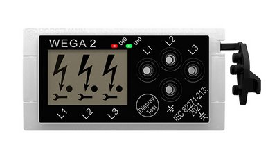
VDIS maintenance records help teams identify repeated defects and prioritize corrective actions. Each entry should include the equipment identifier, inspection date, observed symptoms, environmental conditions, and responsible personnel. Records should distinguish suspected causes from confirmed findings and document repairs, approvals, test results, and unresolved issues. Engineers can compare these records across maintenance cycles to identify recurring moisture ingress or connection problems. Teams should assign each unresolved issue a severity level, a responsible person, and a target completion date. Photographs, test reports, and approved work orders can support the findings. A replacement indicator, such as a 160.5×18.5mm Switchgear Voltage Indicator, still requires dimensional and electrical compatibility checks before procurement approval. The team should preserve original equipment references and record authorized design changes. Supervisors can review overdue actions and recurring faults to evaluate corrective measures and improve long-term reliability.
Which Actions Belong In A Preventive Maintenance Plan?
A preventive maintenance plan should turn inspection findings into specific, verifiable tasks. Teams can use the following actions to maintain consistent practices across switchgear installations.
- Review manufacturer instructions and approved electrical drawings before scheduling work.
- Inspect accessible sensor surfaces, indicator housings, cable entries, and mounting points.
- Record abnormal illumination, moisture, corrosion, loose hardware, and visible insulation damage.
- Perform functional checks with compatible equipment and authorized procedures.
- Correct identified defects and investigate their underlying causes.
- Verify repairs, document test results, and close outstanding maintenance actions.
- Review recurring faults and adjust the maintenance schedule when justified.