How To Check VDIS Compatibility With Switchgear?
VDIS compatibility with switchgear depends on voltage rating, phase arrangement, dimensions, wiring, mounting, and operating environment.
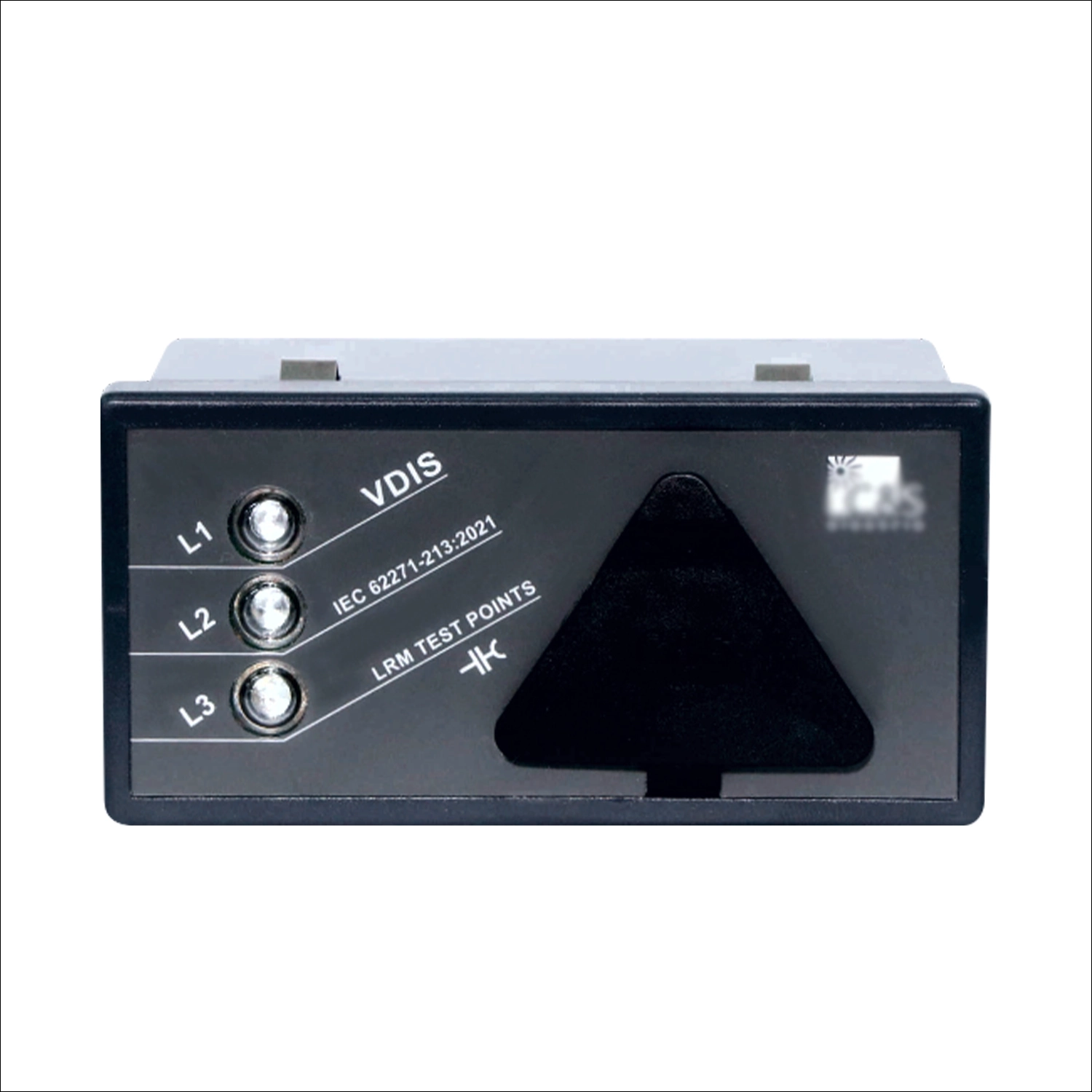
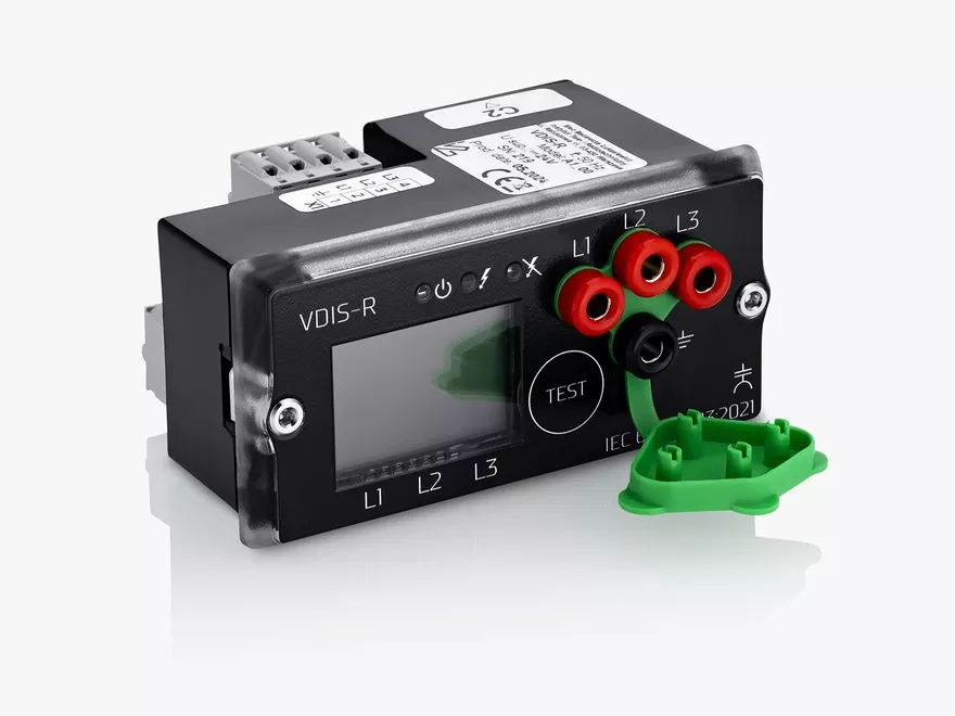
VDIS compatibility with switchgear requires more than matching a voltage rating. Engineers must compare electrical, mechanical, and functional interfaces before installation. Medium-voltage switchgear often contains compact compartments with fixed sensing points and limited panel space. Therefore, even a technically suitable indicator can become unsuitable during retrofit work. The checking process should start with approved switchgear drawings and nameplate information. Engineers should then verify voltage range, phase arrangement, mounting dimensions, terminal configuration, and environmental conditions. Wiring requirements also need careful review because voltage detection circuits differ between assemblies. A supplier should receive enough technical information to verify each interface before production. This approach reduces replacement errors and prevents unnecessary cabinet modifications. It also creates a clear technical record for procurement, inspection, and commissioning.
What Does VDIS Compatibility With Switchgear Mean?
VDIS compatibility describes whether a voltage detection system can operate correctly within a specific switchgear assembly. The relationship includes electrical, mechanical, and functional interfaces. Electrical compatibility covers rated voltage, sensing method, frequency, insulation requirements, and connection arrangements. Mechanical compatibility concerns panel cutouts, mounting holes, depth, and terminal accessibility. Functional compatibility considers phase indication, voltage presence detection, and required operating conditions. Engineers should also examine the relationship between the VDIS and the switchgear's primary sensing components. Capacitive voltage detection points must provide suitable signals for the selected indicator. Incorrect assumptions can produce unreliable indications even when physical installation appears successful. For procurement teams, compatibility should therefore become a documented technical verification rather than a simple product selection step.
Which Switchgear Parameters Should You Confirm First?
The switchgear provides the technical baseline for selecting a suitable voltage presence indicator. Start with the nameplate and approved electrical drawings. Record the rated voltage, frequency, phase configuration, installation type, and auxiliary supply. Identify the exact compartment where the indicator will operate. Check whether the assembly uses capacitive coupling points, voltage transformers, or another sensing arrangement. Existing terminal numbers should also be recorded before any replacement decision. Engineers should avoid relying only on photographs because photographs rarely reveal electrical ratings or internal wiring. The following information provides a practical starting point:
- Rated voltage and maximum operating voltage
- Frequency and phase configuration
- Voltage sensing interface
- Existing terminal arrangement
- Panel cutout dimensions
- Mounting hole spacing
- Installation environment
- Auxiliary supply requirements
These parameters establish the basic compatibility framework before detailed component selection begins.
How Do You Verify The VDIS Voltage Rating?
Voltage rating verification should compare the switchgear system voltage with the indicator's specified operating range. Engineers should distinguish nominal voltage from the highest voltage for equipment. Medium-voltage systems can also use different phase-to-phase and phase-to-earth values. The voltage detection circuit must therefore match the actual sensing arrangement. A mismatch may produce insufficient indication or excessive electrical stress. Frequency should also match the intended application when the sensing technology depends on alternating current characteristics. For example, a procurement team replacing an indicator in a 12 kV indoor switchgear panel should verify the complete sensing circuit. Checking only the 12 kV system label would leave important technical questions unanswered. The team should confirm the sensing interface, insulation coordination, phase connections, and approved operating range before approving the replacement.
How Should The Phase Arrangement Be Checked?
Phase arrangement directly affects the accuracy of voltage presence indication. Engineers should identify the three phase sensing points and their corresponding terminals. Labels such as L1, L2, and L3 should match the switchgear drawings and physical wiring. Some assemblies place sensing points in compact layouts that differ from standard panel arrangements. Therefore, terminal order should never be assumed from the indicator's appearance. Incorrect phase connections can create misleading indications during maintenance or switching operations. A replacement indicator should also support the number of phases required by the assembly. During inspection, technicians should compare the physical terminal sequence with the approved secondary wiring diagram. A 54×32mm Switchgear Voltage Indicator can also require precise phase terminal matching within a compact panel layout. Any difference should be resolved before energization. This simple verification helps prevent wiring errors that mechanical installation alone cannot reveal.
What Mechanical Dimensions Affect VDIS Compatibility?
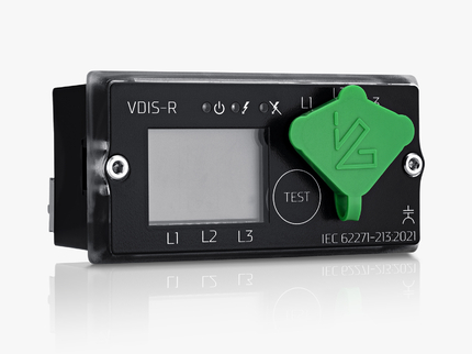
Mechanical dimensions can determine whether a voltage presence indicator fits an existing switchgear panel. Important measurements include the front cutout, mounting-hole pattern, overall depth, and terminal clearance. Engineers should also check the available space behind the panel. Compact switchgear compartments may contain barriers, busbar supports, wiring ducts, and insulation components close to the indicator position. A replacement device with greater depth may interfere with these components. Procurement teams should request dimensional drawings instead of relying on nominal product descriptions. The following comparison shows the main mechanical factors that deserve verification.
| Mechanical Parameter | What To Check | Potential Issue |
|---|---|---|
| Panel cutout | Length and width | Indicator may not fit the opening |
| Mounting holes | Hole spacing and diameter | Existing fasteners may not align |
| Installation depth | Rear clearance | Internal components may obstruct installation |
| Terminal position | Connector orientation | Wiring may require modification |
What Should You Check Against The Switchgear Wiring Diagram?
The wiring diagram provides the most reliable reference for confirming connection compatibility. Engineers should trace each voltage sensing circuit from its origin to the indicator terminals. Phase identification should remain consistent throughout the circuit. Terminal numbers should also match the latest approved drawing revision. A drawing from an earlier cabinet modification may no longer represent the installed arrangement. For this reason, technicians should compare documentation with physical wiring during replacement work. The check should cover sensing terminals, grounding points, auxiliary circuits, and any associated test connections. An Inductive High Voltage Indicator Display may use a different sensing principle from an existing capacitive arrangement. Engineers should never assume that two indicators with similar front-panel functions share identical interfaces. Checking VDIS compatibility against the approved wiring diagram can expose interface differences before installation. Documentation review must therefore precede any wiring modification or production approval.
How Does A Real Switchgear Retrofit Reveal Compatibility Issues?
A practical retrofit project demonstrates why several interfaces must be checked together. Consider an indoor 12 kV switchgear cabinet scheduled for routine component replacement. The maintenance team first recorded the system voltage and three-phase sensing arrangement. They then measured the existing panel cutout and mounting-hole spacing. The initial replacement candidate matched the voltage range but used a different mounting pattern.
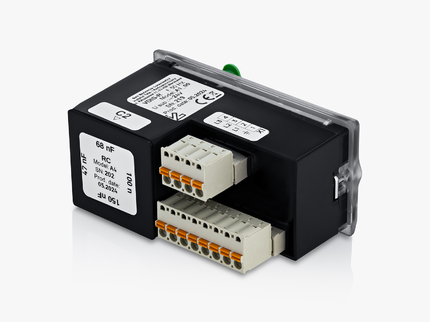
Its rear terminal position also conflicted with the cabinet wiring duct. A dimensional revision resolved the mounting problem, while a revised terminal arrangement simplified the wiring connection. The final inspection then verified phase identification and terminal continuity. This case shows how early technical checks can prevent installation delays and avoid unnecessary panel modifications.
What Documents Should Suppliers Request For VDIS Compatibility?
Suppliers need accurate cabinet information to verify the complete interface. Procurement teams should provide documents and measurements that describe both the electrical system and physical installation. A supplier can then compare the proposed indicator against the actual switchgear configuration.
| Document or Data | Required Information | Verification Purpose |
|---|---|---|
| Switchgear nameplate | Voltage, frequency, equipment rating | Electrical application check |
| Single-line diagram | Primary circuit configuration | System and phase verification |
| Secondary wiring diagram | Terminal numbers and connections | Interface verification |
| Panel drawing | Cutout and mounting dimensions | Mechanical fit verification |
| Existing indicator datasheet | Ratings and connection details | Replacement comparison |
| Site conditions | Temperature, humidity, altitude | Environmental verification |
These documents allow suppliers to identify incompatibilities before production. Clear technical records also reduce repeated questions between procurement, engineering, and maintenance teams.
What Final Checks Should Confirm VDIS Compatibility?
Final verification should combine every previously checked interface into one approval process. Engineers should first confirm electrical ratings against the switchgear nameplate. Next, they should verify phase arrangement and sensing connections against the latest wiring diagram. Mechanical dimensions should then be checked against the actual panel drawing. Environmental requirements should match the installation location and enclosure conditions. The mounting method should also provide sufficient clearance for wiring and inspection. Procurement teams can request a technical drawing for final approval before production. Where practical, an approved sample can provide another reference for dimensional and visual inspection. Installation personnel should retain the final wiring record after commissioning. This process creates traceable evidence that the selected indicator matches the intended switchgear application. It also gives future maintenance teams reliable information for subsequent replacement work.
FAQ
Can Any VDIS Be Installed In Any Medium-Voltage Switchgear?
No. A voltage presence indicator must match the electrical and mechanical interfaces of the target switchgear. Rated voltage represents only one part of the selection process. Engineers should also check phase arrangement, sensing technology, terminal configuration, mounting dimensions, depth, and environmental conditions. Existing capacitive sensing points must provide suitable signals for the selected system. Physical fit matters because compact switchgear compartments often have limited installation space. Wiring compatibility also affects whether a replacement can connect without cabinet modifications. For retrofit projects, the existing drawings and physical measurements should be compared with the supplier's technical documentation. A product can have suitable electrical ratings yet remain unsuitable because of a mounting or terminal mismatch.
What Information Should Be Sent To A VDIS Supplier?
A supplier should receive the switchgear nameplate data, electrical diagrams, panel drawings, and existing indicator information. Rated voltage and frequency establish the basic electrical requirements. Single-line diagrams show the primary circuit configuration and phase arrangement. Secondary wiring diagrams identify sensing terminals and auxiliary connections. Panel drawings provide cutout dimensions, mounting-hole positions, and available depth. Photos can supplement these documents, but they should not replace technical drawings. Environmental conditions should also be provided when the cabinet operates under unusual temperature, humidity, altitude, or pollution conditions. Accurate measurements are especially important for retrofit projects. Providing complete information allows the supplier's engineering team to compare electrical, mechanical, and environmental interfaces before production begins.
Can Existing VDIS Be Replaced Without Modifying The Switchgear?
A direct replacement can be possible when the new indicator matches the existing electrical and mechanical interfaces. Engineers should verify the panel cutout, mounting holes, installation depth, terminal positions, sensing method, and phase connections. Matching the external dimensions alone does not guarantee direct replacement. Terminal differences can require wiring changes, while sensing differences can require a different interface. Retrofit projects should therefore compare the existing device documentation with the replacement drawing. Physical inspection can confirm conditions that older drawings may not show. When the mounting pattern or rear clearance differs, a panel modification may become necessary. Early supplier review can identify these issues before the cabinet is opened. This approach helps maintenance teams plan the work and avoid unexpected installation changes.