How To Control High Display Voltage Presence Safely?
Ensure operator safety with robust High Display Voltage Presence indicators. These passive and active systems prevent switchgear accidents.
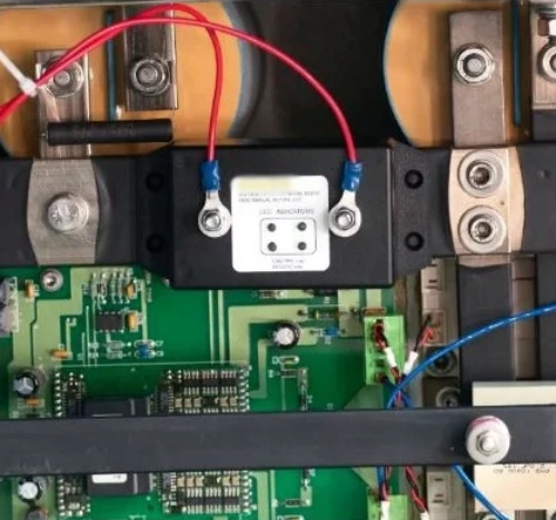
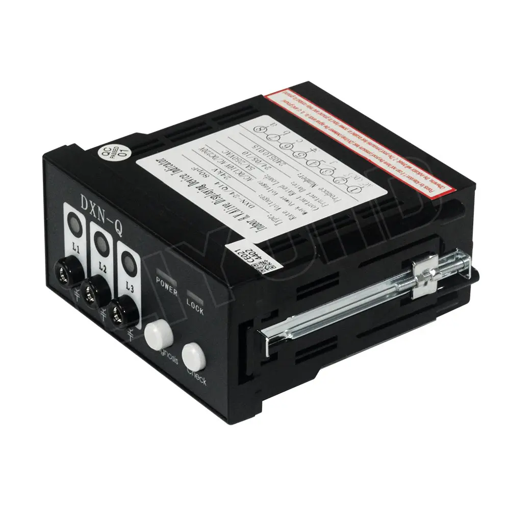
High voltage distribution boards demand reliable security systems for safe daily operations. Operators must verify electrical conditions before initiating any maintenance work on the switchgear. Correct identification of energized lines prevents fatal accidents inside electrical substations. Real-time telemetry monitoring systems offer continuous safety updates to plant engineers. Safe substation management relies on High Display Voltage Presence systems to warn personnel. These active warning devices use capacitive dividers to transmit low voltage signals safely. Visual flashing units alert local workers about dangerous electrical potentials inside the copper busbars. This protective installation ensures total compliance with modern international grid safety standards. Plant managers prioritize these robust visual monitors to eliminate human errors during inspection. Constant visual verification remains the first defense line against unexpected electrical feedback.
Defining High Display Voltage Presence in Modern Power Systems
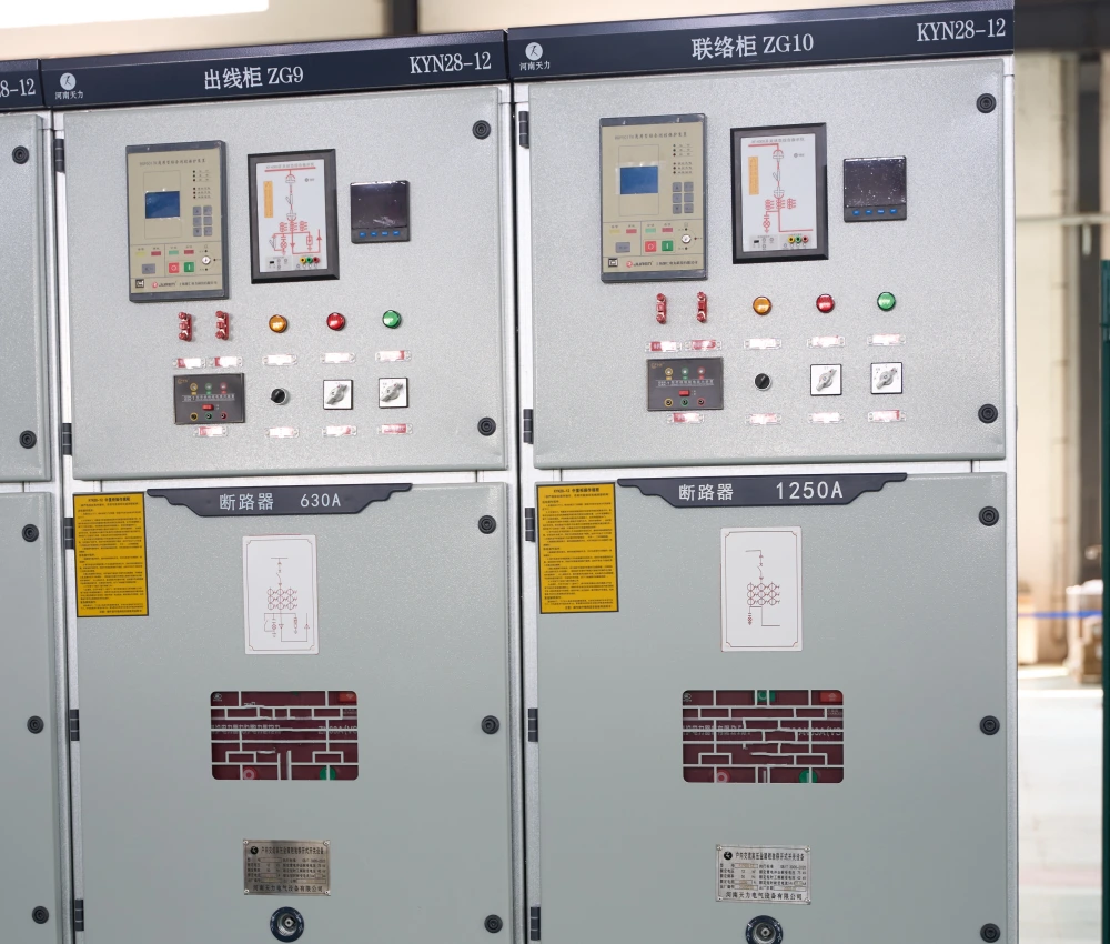
Modern medium voltage installations employ specific coupling electrodes to measure phase potentials. These electrodes couple capacitively with the primary conductors to extract a small measurement voltage. The signal travels through shielded coaxial cables directly to the main control panel indicator. Engineers install a specialized High Voltage Detection And Lcd Display Device (VDIS) for constant tracking. This electronic assembly processes analog input to show real-time phase information clearly. Liquid crystal screens provide precise state readings even under low light workshop environments. Operators view these displays to confirm isolated circuits before applying any grounding tools. Solid state circuitry inside the housing resists electromagnetic interference from adjacent feeders. This hardware layout prevents false signals caused by harmonic distortions inside industrial networks. Electrical safety relies on the precise calibration of these secondary display instruments.
Essential Safety Equipment for Voltage Sensing
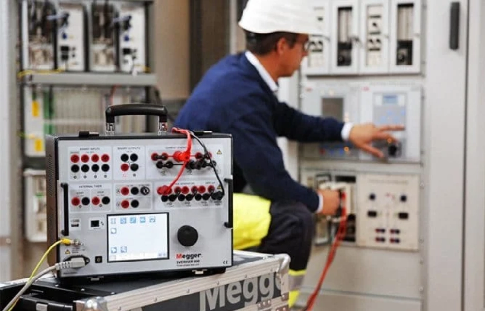
Standard safety processes dictate multiple redundant steps for verification of energized circuits. Technical operators wear heavy dielectric gloves before approaching any metal-clad switchgear. They check the system status indicators to confirm zero energy state across all sections. Redundant test plugs allow external multimeters to verify voltage values at the front panel. This design creates a reliable double check system for utility technicians during field work. Standardized testing minimizes risks during routine maintenance of these highly complex power grids. The following logical sequence outlines the vital steps for secure busbar voltage inspections. Operators must follow these instructions closely to avoid dangerous arc flash incidents. Each step represents a vital safety barrier inside the high voltage zone.
- Inspect physical indicator housings for outer casing cracks or mechanical damage.
- Verify indicator power supply functionality using integrated test buttons on the front panel.
- Measure residual voltage at test sockets using calibrated high-impedance instruments.
- Confirm mechanical padlock engagement on the feeder grounding switch mechanism.
Operational Maintenance Protocols for Voltage Detectors
The listed safety actions maintain the integrity of active voltage detection networks over time. Physical inspection prevents environmental moisture from entering the sensitive electronic component chambers. Dust accumulation on terminal blocks often creates creeping currents and inaccurate diagnostic signals. Regular press-to-test verification confirms that internal neon lamps or display screens work properly. Technicians must replace faulty visual modules immediately to prevent dangerous false negative readings. Using certified measuring tools at the testing sockets provides concrete numerical proof of isolation. This measurement step removes any reliance on visual signals alone during critical operations. Proper padlock procedures secure the switchgear status and protect workers from accidental re-energization. These safety layers guarantee safe working environments near heavy distribution assets.
Comparing Indicators of High Display Voltage Presence
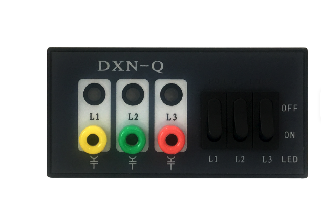
Diverse design options accommodate different grid structures and local substation space limitations. Some substations prefer separate modular indicator panels mounted inside low voltage compartments. Other designs utilize an Integral Lamp Plug-in VDIS for Switchgear units to save panel space. This specific integrated configuration merges the coupling sensor interfaces with the indicator assembly. Such a design minimizes external wiring and reduces the risk of physical signal wire failure. Operators benefit from direct visibility of High Display Voltage Presence status on the switchgear front. Standard models support different auxiliary power supplies to match variable utility station battery setups. Some passive indicator variations run solely on energy harvested directly from the capacitive divider. These self-powered indicators work reliably even during complete station auxiliary power blackout scenarios. Selecting the correct configuration ensures long term grid safety under various grid load conditions.
| Indicator System Type | Standard IEC Voltage Range | Threshold Voltage Limit | Auxiliary Power Need |
|---|---|---|---|
| LRM System (Low Impedance) | 3.6 kV to 40.5 kV | 10% to 45% of Rated Voltage | None (Self-Powered) |
| HR System (High Impedance) | 1 kV to 52 kV | 10% to 45% of Rated Voltage | None (Self-Powered) |
| Active VDIS System | 1 kV to 72.5 kV | 9% to 40% of Rated Voltage | 24V to 220V AC/DC |
Deciphering Technical Parameters of Indicator Standards
The comparison table illustrates critical differences between high-impedance (HR) and low-impedance (LRM) detection standards. LRM networks are safer because they minimize the risk of dangerous electrical shocks to personnel. High-impedance units require careful matching with correct capacitive bushings to prevent system errors. Active display systems operate with external power to support auxiliary signal relays for SCADA integration. These relays transmit live system statuses directly to remote grid control centers for management. Such active devices deliver continuous monitoring of High Display Voltage Presence even during low power cycles. Proper threshold alignment prevents false negative indications when electrical grids experience minor voltage fluctuations. This balance secures substation equipment against sudden flashovers during grounding operations. Plant operators choose indicators depending on existing switchgear interface specifications and installation guidelines.
| Environmental Parameter | Industrial Standard Requirement | Performance Limit |
|---|---|---|
| Operating Temperature | IEC 62271-1 Class Minus 25 | Minus 25 to Plus 55 Celsius |
| Ingress Protection Rating | IEC 60529 Standard | IP40 for Front Panel / IP20 Terminals |
| Dielectric Insulation Test | IEC 61243-5 Standard Section 5 | 2 kV AC for 1 Minute |
Interlocking Logic and Environmental Resistance of Systems
The second environmental table specifies severe operational parameters that safety monitors must withstand daily. Switchgear rooms often experience extreme heat or high humidity depending on their geographic locations. Secure casing seals protect internal solid state relays against dust ingress and humidity condensation. Standard IP40 protection ratings keep solid particles from damaging internal microprocessors during active cycles. Dielectric test standards prove that these indicator units handle unexpected system overvoltages safely. Integrated locking relays connect to the system to control manual grounding switch lock mechanisms. This automated interlock prevents operators from grounding live feeders showing High Display Voltage Presence signs. Mechanical interlock overrides must remain inaccessible to unauthorized staff during standard industrial plant operations. Plant technicians must run periodic dielectric tests to verify insulation safety barriers regularly.
Best Practices for Long Term Substation Safety
Industrial power networks achieve highest reliability through regular testing of secondary indication hardware. Operational managers must implement daily visual logging routines to detect broken display elements. Training workshops ensure that site operators read various state indication displays correctly. Maintenance programs should replace components before they reach the end of their service lives. This proactive strategy keeps substation infrastructure safe from catastrophic electrical faults over time.