How To Maintain Electromagnetic Interlock For Switchgear?
Maintain your electromagnetic interlock for switchgear to prevent dangerous power faults and ensure continuous plant safety.
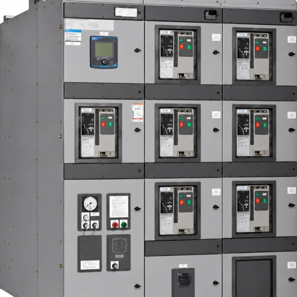
Modern substation operators must maintain high electrical safety standards. Technicians prevent accidental operation of high-voltage circuit breakers through proper care. The electromagnetic interlock for switchgear guarantees secure power distribution. It locks the breaker until safe conditions exist. Dust or moisture can degrade the coil wiring over time. Regular maintenance prevents catastrophic arc flash incidents in the facility. Plant engineers perform daily inspections to ensure reliable operation. This routine preserves expensive assets from mechanical failures. Proper care keeps the safety mechanism working during emergency power cuts. Technical staff must follow manufacturer instructions to avoid hazards. Consistent testing reduces unexpected downtime in industrial environments. Adequate ventilation protects the internal housing from rust. Operators run routine simulations to verify locking functions under load. This process guarantees absolute protection for personnel.

Technical Components Of The Electromagnetic Interlock For Switchgear
The locking mechanism contains several highly specialized mechanical parts. A copper coil creates the magnetic force to retract the locking bolt. The plunger moves smoothly when the control circuit receives voltage. Auxiliary switches track the actual position of the locking pin. These switches send feedback signals to the control room. Stainless steel casings shield the delicate internal solenoid wiring. Technicians inspect the spring mechanism for wear during routine cycles. Weak springs fail to return the bolt to its locked position. This failure poses extreme dangers to the electrical grid. High-quality insulation materials prevent electrical shorts inside the unit. Operators replace worn copper contacts to maintain signal continuity. Tight connections prevent voltage drops during high-load switching tasks. Specialized seals keep grease inside the mechanical linkages. Regular calibration ensures the components operate within design parameters.
Critical Isolation Protocols Before Maintenance
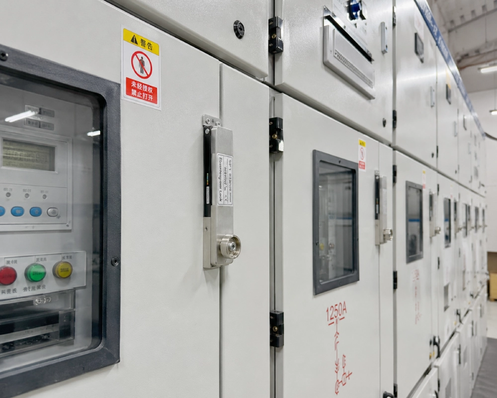
Safety procedures dictate complete isolation before opening high-voltage cubicles. Technicians always disconnect the main power source first. They apply padlock devices to the breaker handles. Grounding switches must discharge residual electrical energy from the busbars. Engineers verify the absence of voltage with calibrated test instruments. Proper isolation protects personnel from unexpected backfeeds. The electromagnetic interlock for switchgear requires control fuse removal. This step prevents accidental solenoid activation during physical contact. Maintenance crews wear flame-resistant clothing during the process. Clear warning signs alert other staff about ongoing work. Working on energized equipment leads to fatal injuries. Only certified personnel should perform these delicate diagnostic steps. Double-checking isolation points guarantees a safe work area. Safe habits ensure a successful maintenance cycle without incidents. Documenting each isolation step maintains compliance with international safety laws.
Visual Inspection Procedures For Solenoids
Inspectors examine the outer casing for cracks or thermal damage. Discoloration on the shell indicates severe coil overheating issues. Dirt accumulation on structural joints prevents smooth mechanical movement. The DSN DM Indoor Electromagnetic Door Lock requires clean contact faces. Dust blocks the magnetic path and reduces locking force. Maintenance teams clean the sealing gaskets with dry cloths. Cracked gaskets allow moisture to corrode the internal plunger. Corrosion causes mechanical sticking during emergency operating modes. Technicians check the tightness of all mounting bolts. Loose bolts misalign the latch with the switchgear frame. Misalignment causes structural friction and wears out the locking bolt. Correcting minor issues during visual checks avoids costly repairs. Every inspector notes the physical condition in logbooks. Clear logs help track degradation trends over long periods.
Testing Electrical Resistance Of Coils
Electrical tests verify the health of the solenoid winding. Technicians set their multimeters to measure resistance values. They compare the reading against the factory reference sheet. Deviations above five percent indicate shorted turns in the coil. Shorted windings draw excessive current and trigger circuit breakers. Low voltage prevents the electromagnetic interlock for switchgear from opening. Insulation resistance testing requires a high-voltage megohmmeter instrument. This test checks the barrier between the coil and frame. A reading below two megohms demands immediate coil replacement. Damp conditions often cause low insulation values in cubicles. Installing small space heaters inside the compartment resolves humidity. Dry coils maintain their dielectric strength under stressful operations. Accurate measurements prevent unexpected coil failures during service. Testing must follow precise electrical safety guidelines.

Essential Tools For Calibrating An Electromagnetic Interlock For Switchgear
Technicians must gather specific tools before starting calibrations. Using the wrong instruments can damage delicate electrical components. Calibrating mechanical components requires precise dimensional measurement gear. Digital calipers measure plunger travel with absolute accuracy. High-grade contact cleaners remove oxidation from auxiliary switches. Micro-ohm meters evaluate contact resistance inside electrical circuits. Torque wrenches secure mounting bolts to factory specifications. Safety glasses protect eyes from flying dust or springs. Insulated tools prevent accidental short circuits during tight adjustments. Non-conductive grease ensures smooth mechanical movement of joints. Testing personnel verify instrument calibration dates prior to testing. Expired calibration certificates compromise the validity of measurements. Having the complete toolset nearby saves time during maintenance. Proper preparation ensures a smooth and efficient testing procedure.
Digital multimeter for measuring coil resistance and voltage
Insulated socket set for securing mounting bolts safely
Fast-drying electrical contact cleaner spray
Synthetic silicon grease for mechanical linkages
Digital calipers for measuring locking bolt travel
Tool Calibration And Maintenance Outcomes
Accurate instruments help maintain the electromagnetic interlock for switchgear efficiently. Digital multimeters track small voltage drops across the terminals. The contact cleaner restores optimal electrical paths without leaving residues. Synthetic silicon grease withstands extreme temperatures inside the metal enclosure. Standard lubricating oils break down under high thermal stress.
Insulated sockets protect workers from accidental contact with energized busbars. Correct torque settings prevent damage to the soft copper threads. Over-tightening deforms the housing and jams the internal plunger. Under-tightening allows vibration to loosen the bolts over time. Vibration-induced loosening leads to mechanical misalignment in the cubicle. Calipers check if the locking bolt retracts completely. Incomplete retraction prevents the circuit breaker truck from racking out. This mechanical lock secures operations in high-voltage facilities. Proper tool selection preserves critical infrastructure for many years.
Mechanical Tolerance Standards For Solenoids
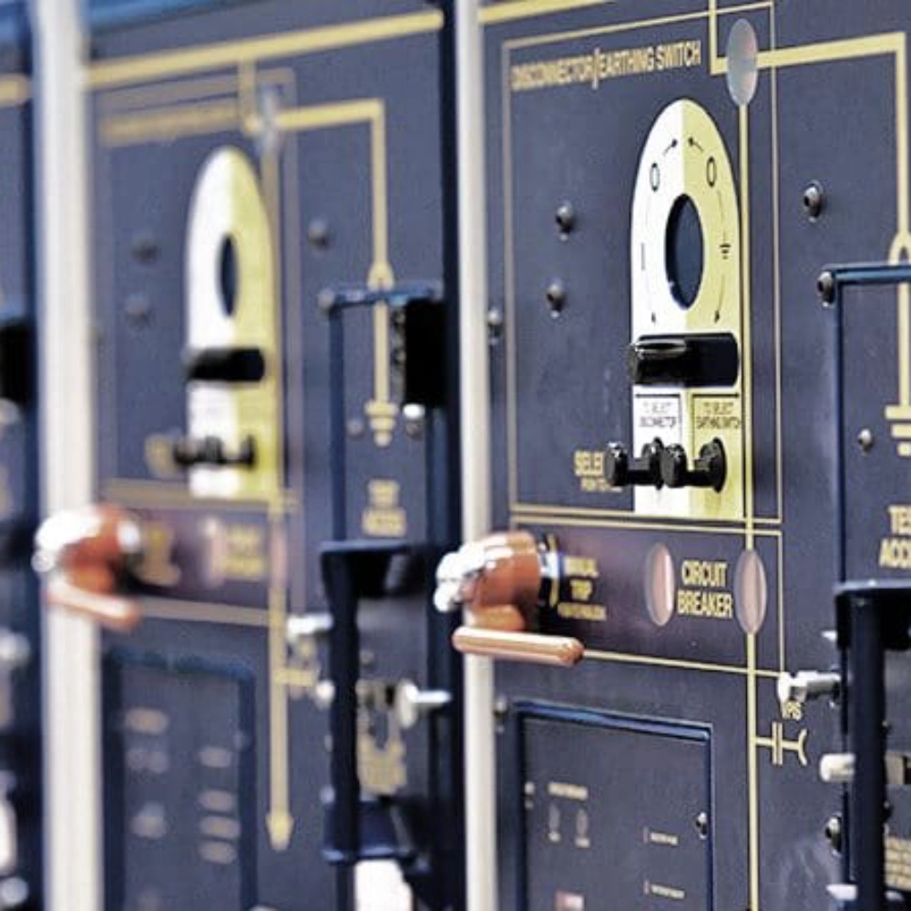
Maintenance crews follow strict mechanical specifications during reassembly. Manufacturer manuals outline exact dimensional tolerances for interlocking systems. Deviating from these metrics causes mechanical jamming of bolts. The locking bolt must extend fully into the mating socket. Plunger travel distance determines the depth of physical locking. Auxiliary switch clearance affects the timing of electrical signals. Delayed signaling prevents the control room from confirming safety states. Operators verify these mechanical parameters with high-precision digital calipers. Spring tension must provide sufficient force to return the bolt. Weak spring force leaves the switchgear in an unlocked state. This condition bypasses physical safety barriers and endangers lives. Correcting mechanical tolerances prevents costly damage to expensive machinery. Consistent mechanical checks guarantee long-term operational success in substations. The following data outlines the typical mechanical parameters.
| Mechanical Metric | Standard Target Range | Critical Warning Threshold |
|---|---|---|
| Plunger Travel Distance | 12.0 mm - 15.0 mm | Less than 10.5 mm |
| Spring Return Force | 15 N - 20 N | Less than 12 N |
| Auxiliary Contact Gap | 2.5 mm - 3.5 mm | Greater than 4.5 mm |
Deciphering Mechanical Tolerance Operational Metrics
The mechanical data highlights crucial thresholds for lock operators. Plunger travel must reach at least twelve millimeters to lock. Shorter travel distances fail to block the mechanical racking mechanism. Spring return force ensures the bolt snaps back during power loss. A spring force below twelve Newtons risks partial lock situations. Partial locks can yield under sudden mechanical vibrations or shocks. Contact gaps inside auxiliary switches dictate feedback response speed. Large gaps delay safety indications to the control computer system. Delayed safety indications disrupt automatic circuit breaker sequence controls. Technical crews adjust contact positions using non-conductive shims. This adjustment ensures absolute compliance with international utility standards. Proper mechanical calibration prevents costly downtime in automated plants. Regular inspections maintain these tight dimensional clearances within limits. Maintaining proper tolerances secures high-voltage panels from physical damage.
Coil Electrical Operational Parameters
Reliable interlocking systems depend on precise voltage inputs. Solenoid coils operate within strict electrical parameters to avoid failure. High voltage causes coil overheating and rapid insulation breakdown. Low control voltage prevents the plunger from moving at all. Maintenance engineers measure coil resistance to evaluate health. Continuous duty cycles require robust solenoid coil designs. Heat dissipation remains a major factor in closed electrical panels. Elevated temperatures accelerate the aging of copper wire insulation. Broken insulation causes internal short circuits and coil failure. Electrical specifications define safe limits for standard substation devices. Operators consult factory sheets before executing high-voltage tests. Testing these metrics ensures high system reliability during faults. The electrical parameters table details these key standard variables. Technicians use these numbers during routine preventive test routines.
| Electrical Parameter | Nominal Value | Acceptable Operational Limit |
|---|---|---|
| Rated Control Voltage | 220 V DC | 187 V - 242 V DC |
| Coil Power Consumption | 15 W | Max 18 W |
| Insulation Resistance | 100 MΩ | Minimum 10 MΩ |

Analyzing Electrical Performance Thresholds
The electrical parameters establish safe limits for solenoid operations. Rated control voltage must stay above eighty-five percent to actuate. Dropouts occur when supply grids experience sudden load spikes. Power consumption remains constant unless internal windings fail. Elevated wattage readings signal short circuits inside the coil casing. Technicians replace damaged coils immediately to safeguard secondary wiring. Insulation resistance must stay high to prevent ground leakages. Low resistance ratings indicate moisture inside the electrical compartment. Moisture degrades the dielectric materials over short operational cycles. Installing anti-condensation heating elements resolves this environmental threat. Safety relays monitor these parameters to protect field equipment. Proper analysis of electrical data prevents thermal runaways. This preventative approach ensures steady operation in modern substations. Consistent tracking of electrical metrics maintains continuous power flows.
FAQ
What causes an electromagnetic interlock to fail to release?
Several common issues prevent the solenoid plunger from retracting properly. Voltage drops represent a frequent electrical cause of failure. The coil cannot generate enough magnetic force without nominal voltage. Damaged auxiliary contacts disrupt the electrical circuit sequence completely. Mechanical friction also blocks plunger movement inside the housing. Dried grease and dirt accumulate on the sliding shafts over time. Misaligned frames put physical pressure on the latch mechanism. This misalignment binds the bolt and stops magnetic actuation. Technicians clean and lubricate these parts to restore proper operation. Regular testing prevents these locking issues from disrupting substation safety.
How often should you test the interlocking solenoid coil?
Maintenance schedules dictate testing intervals based on environmental conditions. Standard substations require thorough testing at least once a year. Harsh industrial plants demand more frequent checking procedures. Facilities with high humidity inspect the solenoids every six months. Daily visual checks verify physical alignment and casing integrity. Operators test electrical resistance values during annual outage periods. Checking insulation resistance prevents sudden failures under load. Frequent switching operations increase mechanical wear on internal springs. High-use panels require closer observation to maintain reliability. Precise records help schedule parts replacement before failures happen. Consistent testing ensures safety barriers protect plant personnel.
Can you manually override a faulty switchgear safety interlock?
Operators can manually bypass the locking system during rare emergency situations. Authorized personnel must approve every override action beforehand. Safety procedures require written permits prior to manual activation. Technicians use a mechanical bypass key to release the bolt. Unlocks performed without proper authorization pose severe electrocution hazards. Operators must check the status of local breakers first. Bypassing the system with energized busbars can cause massive explosions. Mechanical overrides remain a temporary solution during repairs. Staff must fix the faulty coil immediately after operation. Restoring automatic safety functions secures the electrical substation long-term. Relying on manual overrides violates standard utility safety policies.