How To Troubleshoot Common VDIS Problems?
VDIS troubleshooting helps identify display faults, sensor problems, wiring issues, and testing errors in medium-voltage switchgear.
Introduction: Common Challenges in VDIS Fault Diagnosis
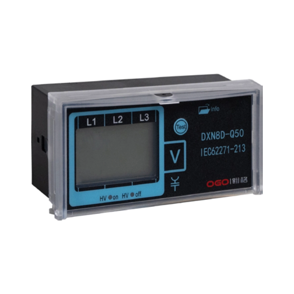
VDIS troubleshooting helps technicians identify faults affecting voltage indication in medium-voltage switchgear. A Voltage Detecting and Indicating System (VDIS) provides a visual indication of voltage presence through sensors and indicator units. Common problems include missing signals, inconsistent phase indications, damaged connections, and abnormal displays. These symptoms can result from electrical faults, environmental conditions, installation errors, or component deterioration. However, an abnormal indication does not necessarily mean that the primary circuit has lost voltage. Technicians must distinguish between indicator failures and actual electrical conditions. Effective diagnosis requires technical documentation, appropriate testing equipment, and strict safety procedures. A systematic approach reduces unnecessary component replacement while supporting reliable maintenance decisions.
What Causes Common VDIS Problems?
Several factors can affect the performance of voltage indication systems in medium-voltage switchgear. Capacitive sensors may experience connection problems, contamination, insulation deterioration, or mechanical damage. Signal cables can develop loose terminals, broken conductors, or degraded insulation. Indicator units may also suffer from damaged electronic circuits, defective display elements, or incompatible connections. Environmental conditions introduce additional risks. Condensation can promote corrosion, while excessive temperatures may accelerate component aging. Incorrect installation can create similar symptoms, especially when technicians overlook wiring diagrams or rated interface specifications. Identifying the underlying cause requires examining the complete sensing and indication arrangement. Replacing the display alone may not resolve faults originating in the sensor circuit.
How Does VDIS Troubleshooting Improve Electrical Safety?
VDIS troubleshooting supports maintenance decisions, but technicians must recognize its limitations. A voltage presence indicator does not replace approved procedures for establishing an electrically safe work condition. A blank display may indicate a failed sensor connection rather than an absence of voltage. Similarly, an illuminated indicator does not independently establish every condition required for safe maintenance. Personnel must follow site-specific isolation procedures and verify de-energization using approved equipment. Testing methods must match the equipment design and applicable safety requirements. Technicians should never disconnect sensing cables or open energized compartments simply to investigate an abnormal indication. Qualified personnel must assess hazards, establish required protective measures, and consult manufacturer instructions before performing diagnostic work.
How to Approach VDIS Troubleshooting for Display Faults?
A disciplined diagnostic sequence helps technicians narrow down possible causes without replacing components unnecessarily. Begin by recording the symptoms, affected phases, operating conditions, and any recent maintenance activities. Compare the observed behavior with the approved wiring diagram and equipment documentation. Next, inspect accessible indicator housings, cable entries, and connections for visible damage, corrosion, or moisture. Qualified personnel can then perform permitted checks according to the manufacturer's procedures. They should distinguish between a failed display, an interrupted signal path, and a sensor-related fault. The following table summarizes common symptoms and their possible causes. These associations help prioritize inspections, but they do not establish a definitive diagnosis without suitable verification.
| Observed symptom | Possible cause | Recommended diagnostic direction |
|---|---|---|
| No indicator illumination | Failed display, disconnected cable, or defective interface | Check approved connection diagrams and inspect accessible components |
| One phase shows no signal | Phase-specific sensor or connection fault | Compare the affected channel with the other phases |
| Intermittent indication | Loose connection, damaged cable, or unstable coupling | Inspect the signal path under approved maintenance conditions |
| Unexpected indication | Incorrect wiring, incompatible components, or sensor damage | Verify component specifications and installation records |
| Visible condensation | Moisture ingress or inadequate environmental control | Investigate enclosure sealing and humidity management |
How to Investigate Incorrect or Unstable Voltage Indications
Unstable indications require careful investigation because several faults can produce similar symptoms. A loose terminal may interrupt the signal intermittently, particularly when vibration affects an existing connection. Damaged insulation or moisture contamination can also influence electrical performance. In capacitive sensing arrangements, the sensor geometry and intended electrical coupling affect the signal delivered to the indicator. Technicians should therefore verify the specified sensor arrangement rather than assuming every sensor uses identical characteristics. For example, a replacement indicator may appear compatible but perform incorrectly with an unsuitable sensing interface. Maintenance personnel should review component specifications, connection diagrams, and historical fault records. Any electrical measurements must follow approved procedures and equipment-specific requirements.
How to Identify Sensor and Wiring Faults
Capacitive sensing systems rely on components that couple electrically to the primary circuit without requiring direct conductive contact with its live conductor. Their performance depends on the intended design, installation geometry, insulation condition, and associated connections. During VDIS troubleshooting, technicians should inspect accessible sensor terminals, cable joints, connectors, and indicator interfaces for corrosion, damaged insulation, loose mounting hardware, and moisture. They must also check whether previous maintenance introduced incorrect connections or unsuitable replacement components. Where documentation specifies electrical tests, qualified personnel should use approved methods and instruments. An insulation test or continuity measurement must never be applied indiscriminately to connected electronic equipment. The manufacturer determines which components require isolation before testing.
How to Troubleshoot Phase Indication Abnormalities
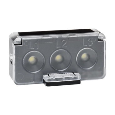
Three-phase switchgear requires consistent interpretation of the relevant phase indications. When two phases appear normal but the third shows no signal, technicians should investigate the affected channel systematically. Potential causes include a defective sensor, interrupted wiring, a poor terminal connection, or a damaged indicator input. However, the displayed pattern alone cannot identify the exact failure location. Personnel should compare the installed arrangement with the approved phase identification and wiring documentation. They must also consider whether the equipment design uses independent sensing paths or shared interfaces. A 160.5×18.5mm Switchgear Voltage Indicator must match the specified installation dimensions and sensing interface to support reliable phase indication. Approved inspection and verification procedures should establish the cause before any component replacement or return to service.
How to Check VDIS Compatibility and Installation Errors
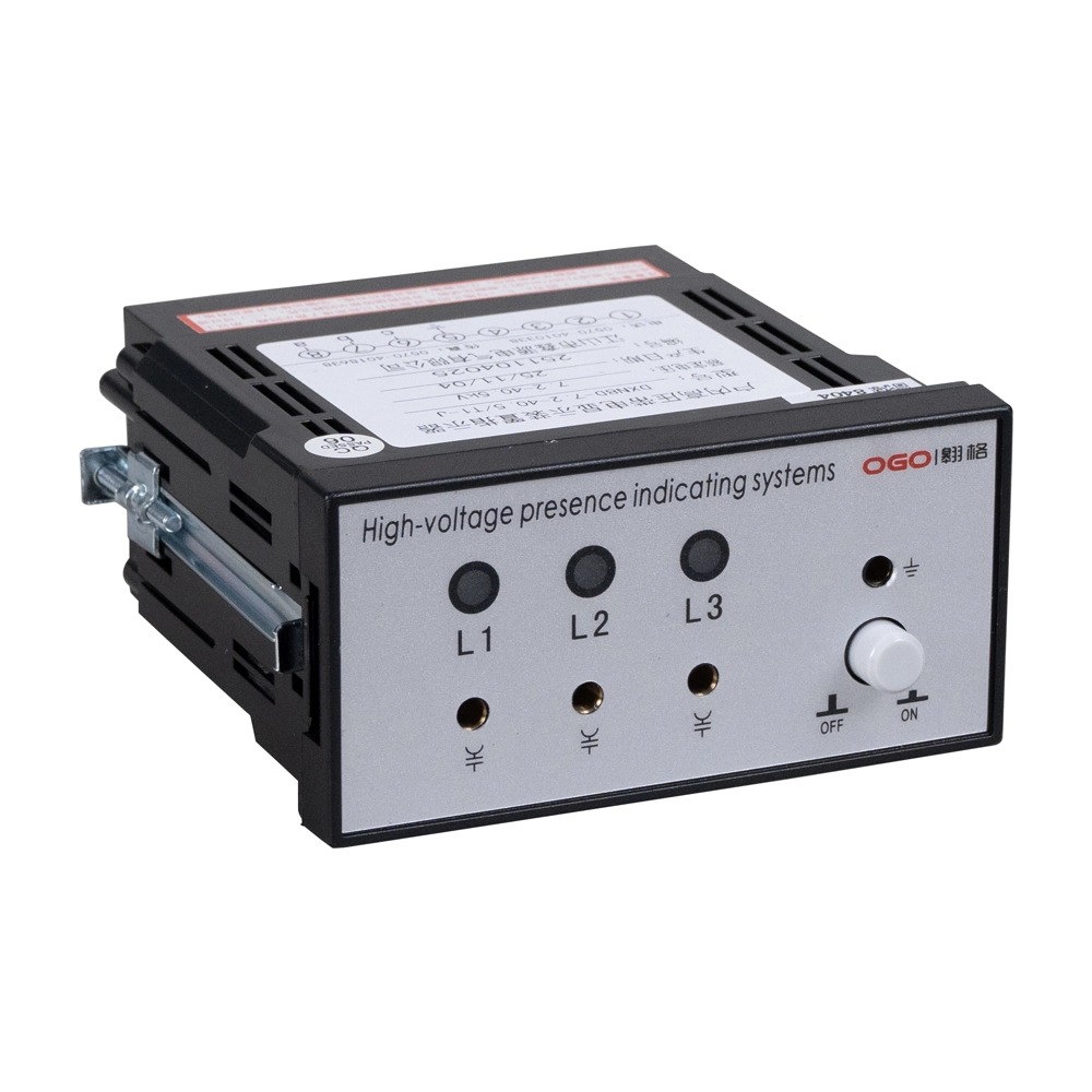
Compatibility problems often arise when technicians replace indicators or sensors without confirming their electrical specifications. Relevant parameters may include the intended voltage class, sensor interface, capacitive coupling characteristics, connector arrangement, and mounting dimensions. Mechanical compatibility alone does not guarantee correct electrical performance. For example, a 92×44mm LCD High Voltage Indicator Display may require specific mounting dimensions and electrical interface compatibility, so technicians should verify both parameters before replacement. Installation errors can also occur when technicians reverse connections or overlook phase identification. A replacement should match the approved equipment configuration and manufacturer requirements. The following examples illustrate specification checks that can prevent avoidable installation problems. Actual acceptance criteria depend on the switchgear design and the relevant technical documentation.
| Component or parameter | What to verify | Why verification matters |
|---|---|---|
| Indicator unit | Interface specifications and mounting dimensions | Prevents mechanical or electrical incompatibility |
| Capacitive sensor | Specified sensing arrangement and rated application | Supports the intended signal coupling |
| Signal cable | Connection type, insulation condition, and routing | Reduces signal interruption and insulation risks |
| Phase connections | Phase identification and wiring diagram | Helps prevent incorrect phase indications |
| Replacement parts | Approved specifications and manufacturer compatibility | Reduces repeat faults after maintenance |
What Tools Are Needed for VDIS Fault Diagnosis?
Suitable diagnostic tools depend on the fault, switchgear design, and permitted maintenance procedures. For effective VDIS troubleshooting, technicians should have access to approved wiring diagrams, component datasheets, maintenance records, and appropriate inspection equipment. A flashlight can help identify damaged insulation, corrosion, and moisture around accessible components. Manufacturer-approved test equipment may support specified electrical checks when qualified personnel follow the required procedures. Instruments must have suitable ratings for the intended application. Technicians should also use the protective equipment and isolation arrangements required by the site's electrical safety rules. A digital multimeter is not automatically suitable for every part of a voltage indication circuit. Personnel must confirm its permitted use before connecting it to any component.
How to Troubleshoot VDIS Problems Through a Practical Field Case
Consider a representative maintenance scenario involving a medium-voltage switchgear panel. Operators report that one phase indicator occasionally loses its signal, although the other two indications remain consistent. The maintenance team records the affected phase and checks recent maintenance history. After establishing the required safe work conditions, qualified technicians inspect accessible connections and compare them with the approved wiring diagram. They identify a loose connection in the affected signal path. The team corrects the connection according to the manufacturer's instructions and examines the surrounding cable for damage. Subsequent checks follow the approved verification procedure before the panel returns to service. This illustrative case shows a plausible diagnostic process, not a documented customer incident. Actual faults require independent confirmation.
How to Prevent Recurring VDIS Faults
Preventive maintenance can reduce recurring indication problems and help technicians identify deterioration before failures become disruptive. Inspection intervals should reflect manufacturer recommendations, site conditions, operating experience, and applicable maintenance requirements. Personnel should examine accessible connections, cable entries, enclosure seals, and indicator housings during scheduled inspections. Moisture management deserves particular attention in installations exposed to condensation or significant temperature fluctuations. Maintenance teams should also record repeated symptoms, replacement parts, and corrective actions. These records can reveal patterns that isolated inspections might overlook. During component replacement, technicians must confirm compatibility before installation. Preventive maintenance should never involve opening energized compartments or disturbing electrical connections without the required authorization, isolation, and protective measures.
What Should Technicians Record After Fault Diagnosis?
Accurate maintenance records help teams compare faults across different inspections and equipment operating periods. Each record should identify the affected panel, observed symptom, relevant phase, inspection date, and operating conditions. Technicians should document the diagnostic steps performed and distinguish confirmed causes from suspected explanations. Any replaced components should include their specifications and installation details. Verification results must also reference the approved procedure or applicable acceptance criteria. If the original symptom returns, these records help personnel identify recurring connection problems or unsuitable replacement parts. Clear documentation also supports maintenance planning and technical audits. Teams should retain records according to site policies and applicable requirements. Complete records improve traceability without replacing the technical judgment of qualified personnel.