What Features Matter In High Voltage Indicator Display?
Evaluate critical features of a High Voltage Indicator Display to ensure substation safety and continuous grid monitoring.
Essential Functions Of A High Voltage Indicator Display
Modern electrical switchgears require constant monitoring to protect operators from lethal shock hazards. A reliable High Voltage Indicator Display provides continuous visual confirmation of live physical busbars inside sealed enclosures. Technicians depend on these safety devices during routine substation inspections and maintenance routines. The interface monitors capacitive voltage dividers to detect the presence of dangerous electrical energy. Visual alerts warn operators even before they attempt to open metal-clad switchgear doors. This real-time visibility prevents catastrophic accidental contact with energized conductor bars. Industrial safety protocols mandate these visual alert tools in modern power distribution grids. Operational safety improves drastically when engineers install robust signaling devices in switchgear systems. Uninterrupted operation ensures that maintenance crews always remain safe during standard field operations.
Operating Principles Of Modern Visual Indicators
Capacitive coupling systems extract a safe signal from high-voltage primary conductors. The High Voltage Detection And Lcd Display Device (VDIS) processes this low energy signal to drive visual components. Liquid crystal elements show active voltage states clearly under diverse ambient light settings. Engineers calibrate these systems to trigger visual alarms when voltage exceeds defined thresholds. These units do not need an external auxiliary power supply to display presence. Energy harvested directly from the live busbar powers the flashing warning icons. Maintenance teams can easily verify conductor status without using handheld test probes. High-quality designs resist electromagnetic interference from nearby switching operations inside the substation. This internal shielding prevents false indications during severe grid faults. Active components ensure precise voltage state reporting under all normal operating conditions.
Key Technical Parameters For Equipment Evaluation
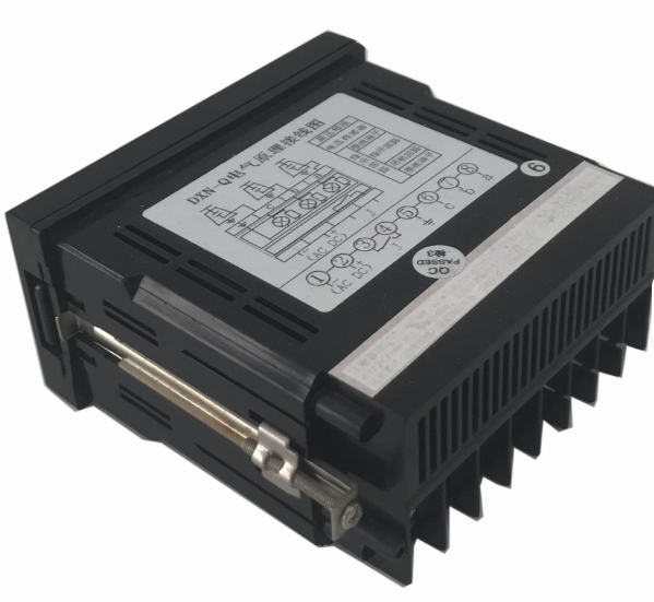
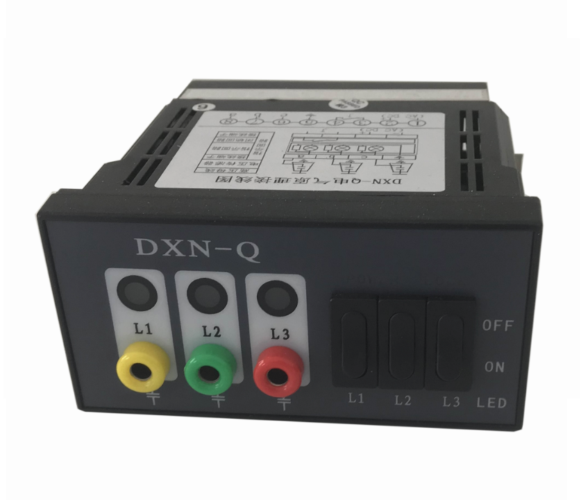
Procurement officers evaluate critical technical attributes during the equipment selection phase. A standard High Voltage Indicator Display must withstand significant nominal voltage levels without degradation. Phase matching features allow workers to perform synchronization checks directly on the front panel interface. Standardized plug connections ensure quick installation during switchgear panel assembly processes. High insulation resistance protects low-voltage measuring circuits from high-energy transient spikes. Manufacturers use robust materials to build enclosures that resist extreme temperature fluctuations. Cold winter environments and hot tropical summers will not affect the measuring accuracy. Reliable terminal blocks simplify wiring to the external capacitive dividers. These physical design parameters determine how long the safety indicators will function in the field. Correct choices minimize system downtime and enhance overall facility safety.
Auxiliary Power Configurations For Signal Redundancy
Auxiliary energy provides essential support for advanced monitoring functions in digital switchgears. The Integral Lamp Plug-in VDIS for Switchgear utilizes auxiliary inputs to illuminate bright warning lamps. These dual-source configurations ensure visual alerts remain active during complete grid outages. Maintenance engineers view the lamp status to confirm that busbars are safe to touch. Integrated electronic circuits manage the power source switching smoothly without causing signal interruption. Relay outputs can trigger external alarms in the central control room when power fails. Technicians rely on these visual backups during emergency shutdown scenarios. This continuous safety feedback loop prevents accidental injury during complex panel maintenance tasks. Modern utility installations specify these integrated units to maximize station reliability. Smart auxiliary systems also transmit operational data to utility management centers.
Performance Characteristics of Visual Detection Systems
- Test Socket Design: Labeled sockets enable easy phase comparison activities.
- Threshold Ranges: Indicators signal active voltage states above statutory limits.
- Response Speed: Visual feedback activates within milliseconds of busbar energization.
- Enclosure Protection: IP65 ratings prevent dust entry in outdoor switchgear cabinets.
- Auxiliary Contact: Built-in relays send safety signals to external interlocking mechanisms.
Deep Evaluation Of Signal Response And Safety Interface Features
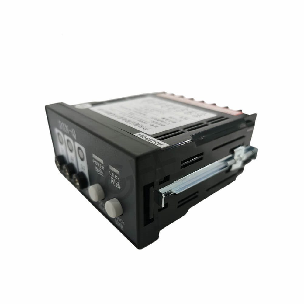
Industrial operators demand highly responsive visual interfaces to maintain strict facility security. A robust High Voltage Indicator Display processes busbar signals rapidly to ensure instantaneous safety warnings. Test socket installations allow field operators to measure actual phase parameters with portable instruments. This mechanical accessibility eliminates the need to expose dangerous live copper connections. Integrated dry contact relays switch states automatically when voltage drops below critical safety limits. Automation systems receive these remote signals to control physical door locks and panel interlocks. Superior ingress protection keeps fine dust out of the sensitive electronic modules. These technical features collectively minimize equipment failures in extremely harsh environment scenarios. Plant safety coordinators prioritize these physical attributes when selecting components for switchgear upgrades.
Quantitative Performance Thresholds and Technical Limits
| System Parameter | Minimum Value | Maximum Value | Standard Compliance |
|---|---|---|---|
| Nominal Voltage Limit | 1.0 kV | 52 kV | IEC 61243-5 |
| Threshold Indication | 10% Un | 45% Un | IEC 62271-206 |
| Relay Contact Rating | 2 A | 5 A | IEEE C37.90 |
Analysis Of Operational Thresholds and Nominal Voltage Limits
Electrical parameters dictate how safety interfaces respond under variable grid conditions. Selecting an appropriate High Voltage Indicator Display requires deep grasp of system voltage threshold values. The table details critical thresholds where visual indicators must trigger active alerts. Standard units must display clear presence signals when the voltage exceeds forty-five percent of nominal ratings. Conversely, the indicator must turn off when voltage drops below ten percent. This tight voltage window prevents false alarms and ensures accurate live line signaling. Built-in relay contacts must handle continuous load currents without contact degradation or melting. Operators depend on these quantitative limits to ensure safe manual grounding procedures. Engineers consult these exact datasets during primary distribution switchgear design procedures. Adhering to these electrical ratings guarantees reliable switchgear behavior during power surges.
Environmental Protection and Enclosure Characteristics
| Environmental Parameter | Standard Class | Performance Level | Target Application |
|---|---|---|---|
| Operating Temperature | Class Minus 25 | -25°C to +55°C | Outdoor Substation Panels |
| Ingress Protection Rating | IP54 / IP65 | Dust and Splash Proof | Industrial Plant Environments |
| Humidity Tolerance | Relative Humidity | Up to 95% RH | Tropical Utility Stations |
Deep Evaluation Of Environmental Resilience Parameters
Substation equipment must endure demanding environmental challenges in modern utility networks. A durable High Voltage Indicator Display functions reliably despite extreme temperature shifts and high relative humidity. The environmental comparison table details how protection ratings shield internal microelectronics from damage. Heavy condensation can form inside outdoor metal cabinets during rapid morning temperature rises. Industrial enclosures with IP65 ratings prevent moisture entry, avoiding short circuits on terminal blocks. Polycarbonate front panels resist ultraviolet degradation when exposed directly to sunlight. Standard models withstand continuous physical vibration caused by nearby heavy circuit breaker operations. Maintenance crews do not need to replace parts frequently when housings offer solid mechanical durability. Selecting high-grade enclosures protects visual systems from corrosive industrial atmospheres and gaseous air. This material resilience ensures decades of uninterrupted service life in petrochemical refineries.
Standard Verification For High Voltage Indicator Display
International testing agencies establish strict guidelines to evaluate electrical safety devices. Compliance with global industrial standards like IEC 61243-5 ensures safety during operation. These standards mandate rigorous dielectric tests to verify insulation barrier performance.
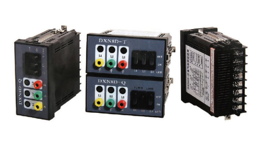
Environmental vibration simulations confirm mechanical durability during heavy short-circuit electrical stress. Independent certification bodies provide verified certificates to confirm compliant performance characteristics. Utility managers prioritize certified visual monitoring tools to minimize installation risks in new substations. Standardized testing also guarantees perfect compatibility with various capacitive coupling devices. Engineering teams inspect these safety certificates before placing purchase orders for distribution networks. Purchasing fully compliant indicator hardware reduces operational hazards significantly across the grid. Operators experience peace of mind when they work near certified medium voltage gear.
FAQ
How do capacitive coupling systems feed voltage indicators?
Capacitive insulators capture small amounts of electrical energy directly from the live main busbars. This low energy signal flows safely to the High Voltage Indicator Display panel. The device converts this incoming signal to activate visual warning lights. These systems operate passively without requiring any connection to external auxiliary power sources. Technicians can check active voltage states even when substation power is totally cut. Standard coaxial cables transmit this signal to prevent high frequency electromagnetic noise interference. Coaxial conductors provide strong shielding against background electromagnetic interference inside the metal cabinet. Engineers select heavy-duty copper terminals to establish continuous paths for high-frequency measurements.
Why are auxiliary dry contacts important in substation safety?
Auxiliary contacts provide dry switching signals to external automation systems and physical locking mechanisms. These contacts change their state automatically when visual indicators detect the presence of dangerous line voltage. Programmable logic controllers read these physical inputs to prevent operators from opening energized switchgear panel doors. This mechanical integration prevents dangerous operating errors during stressful repair tasks. Remote control rooms also monitor these relay outputs to maintain real-time substation safety records. Quality contacts feature durable gold plating to prevent corrosion in humid environments. Secure relays bolster station safety by preventing manual overrides of safety locks. Continuous monitoring of these terminal interfaces ensures immediate failure alerts to remote technicians.
What does standard IEC 61243-5 verify in visual indicators?
Standard IEC 61243-5 defines strict performance parameters for high-voltage detection systems. It verifies the exact threshold levels for safe visual state changes. This standard tests the High Voltage Indicator Display under extreme environmental stress to prove operational reliability. Certified laboratories run dielectric strength tests to ensure user safety against high-voltage surges. They also verify that the visual interface is perfectly readable in bright daylight and pitch darkness. Compliance with this international standard guarantees that the safety hardware performs reliably in key industrial locations. Utility companies trust certified devices to maintain long-term protection inside critical power distribution networks. Safety coordinators prefer these tested units for high-risk substation installations.