What Is An Earth Fault Indicator TNB System?
Earth fault indicator TNB systems support rapid cable fault isolation, stable feeder operation, and utility network reliability.

Power distribution networks require rapid fault isolation during cable failures. An earth fault indicator tnb system helps utility operators locate feeder problems before outages spread across multiple substations. TNB distribution infrastructure includes underground cables, ring main units, switchgear panels, and compact substations. Fault indicators improve operational efficiency by reducing manual inspection time. Utility engineers often deploy these devices along medium-voltage feeders with complex branching structures. Modern monitoring equipment supports visual alarms, remote communication, and transient fault recording functions. Distribution operators also use intelligent monitoring hardware to reduce maintenance costs across dense urban networks. Reliable fault localization protects transformers, cable insulation, and switching equipment from extended electrical stress during abnormal grounding conditions.
Why Modern Utility Networks Require Accurate Fault Detection
Urban distribution systems contain extensive underground cable routes and compact switching stations. Power interruptions inside industrial zones create financial losses for factories and infrastructure operators. Electrical faults often develop because of insulation aging, moisture penetration, conductor damage, or joint overheating. Utility companies require rapid sectional isolation to maintain stable feeder continuity. Advanced monitoring devices reduce troubleshooting time after unexpected cable failures. Engineers also depend on fault indicators during storm recovery operations and network restoration procedures. Many medium-voltage systems operate with limited maintenance windows across dense metropolitan regions. Accurate detection technology helps field technicians identify affected cable sections without unnecessary excavation activities. Stable network performance also supports hospitals, transportation facilities, and commercial manufacturing operations throughout expanding utility service territories.
What Is an Earth Fault Indicator TNB System
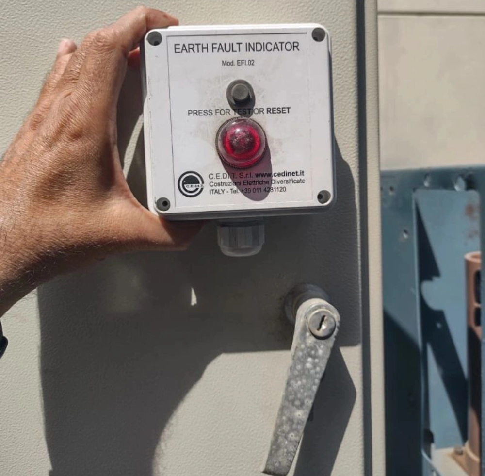
An earth fault indicator tnb installation identifies abnormal current flow caused by grounding failures inside distribution feeders. These systems usually operate within 11kV, 22kV, or 33kV utility networks connected to substations and ring main units. Sensors monitor current imbalance conditions between conductors and grounding paths. Once abnormal conditions appear, the indicator activates visual warnings or communication signals for maintenance teams. Some models support directional fault detection for complex feeder arrangements with multiple power sources. Modern units also integrate with SCADA infrastructure for centralized network supervision. Utilities prefer automated detection because manual cable tracing requires substantial labor and restoration time. Intelligent monitoring equipment improves service continuity across industrial districts, commercial facilities, and large residential distribution environments.
Core Components Inside Fault Monitoring Equipment
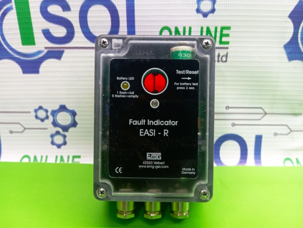
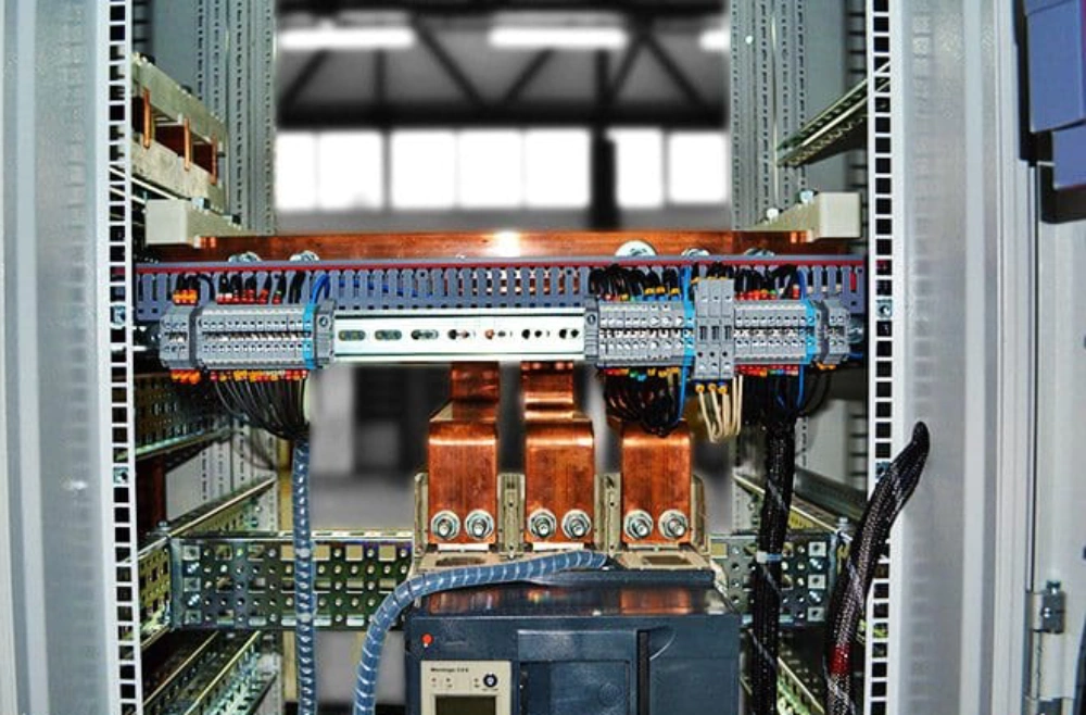
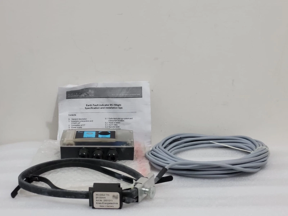
Fault monitoring systems contain several electrical and electronic components designed for outdoor utility environments. Current transformers measure conductor behavior during overloads and grounding disturbances. Sensor modules analyze transient conditions and determine fault direction across feeder branches. Rugged enclosures protect internal electronics from rain, humidity, ultraviolet exposure, and airborne contaminants. Many utilities install LED alarm indicators for quick field identification during nighttime maintenance work. Communication modules transmit operational status through GSM, RF, or fiber-optic infrastructure. Backup batteries maintain alarm operation during complete feeder interruptions. Some monitoring solutions include event recording memory for diagnostic analysis after restoration procedures. Utilities frequently pair intelligent devices with Short-Circuit Grounding Fault Indicator for Cables in underground network sections requiring high detection precision and stable operational reliability.
How Fault Detection Operates During Ground Failures
Ground faults create abnormal current pathways between conductors and earth connections. Monitoring sensors immediately detect imbalance conditions inside medium-voltage distribution circuits. Once detection thresholds exceed preset values, the indicator activates warning signals for operational teams. Certain models distinguish between transient disturbances and permanent grounding faults through programmable timing logic. Directional systems identify fault flow orientation, helping technicians isolate damaged cable sections faster. Intelligent equipment also records fault magnitude, activation duration, and reset conditions for maintenance evaluation. Remote communication platforms transfer operational alarms directly into utility control centers. Fast fault localization minimizes unnecessary feeder shutdowns across industrial districts and urban commercial infrastructure. Efficient restoration procedures improve network reliability while reducing operational pressure on maintenance personnel during emergency repair activities.
Earth Fault Indicator TNB Installation Standards in Malaysia
An earth fault indicator tnb configuration normally follows utility specifications related to insulation performance, environmental resistance, and operational sensitivity. Malaysian distribution systems commonly use compact ring main units and underground cable feeders inside metropolitan areas. Equipment must tolerate high humidity, elevated temperatures, and seasonal rainfall conditions. Many utilities follow IEC standards covering insulation coordination, switching equipment compatibility, and electromagnetic protection performance. Engineers also evaluate ingress protection ratings before approving outdoor installations. Reliable grounding structures remain essential for accurate sensor operation and personnel safety. Cable joint quality strongly influences long-term monitoring stability across medium-voltage infrastructure.

Utilities often perform commissioning tests before network energization to confirm correct alarm operation, communication stability, and directional detection performance under simulated grounding conditions.
Communication Technologies Used in Smart Distribution Networks
Modern utility infrastructure depends heavily on communication integration for real-time monitoring functions. Smart fault indicators often connect with SCADA platforms through GSM, RF, Ethernet, or fiber communication channels. Remote visibility allows operators to evaluate feeder conditions without immediate field deployment. Automated alarms reduce outage response time during severe weather incidents or cable failures. Some systems support cloud-based diagnostics for maintenance planning and operational analysis. Utilities increasingly deploy IoT-compatible monitoring devices inside digital substations and smart distribution projects. Communication redundancy improves reliability during emergency restoration activities. Certain advanced monitoring products integrate Current Temperature Fault Online Monitor functions for thermal supervision across heavily loaded feeder sections. Combined monitoring architecture supports predictive maintenance strategies and reduces unexpected cable breakdown risks within critical industrial environments.
Performance Differences Between Overhead and Underground Networks
Overhead and underground systems experience different operational challenges during grounding failures. Underground cables typically produce faults caused by insulation degradation, moisture penetration, or thermal stress accumulation. Overhead conductors often experience flashovers during storms, vegetation contact, or lightning exposure. Underground restoration usually requires specialized diagnostic procedures and excavation activities. Fault indicators help utilities reduce unnecessary cable excavation by identifying affected feeder segments more accurately. Overhead maintenance teams often rely on visual inspection combined with sectional switching procedures. Underground systems demand higher installation costs but provide stronger environmental protection and improved urban aesthetics. Utilities increasingly deploy automated monitoring equipment because dense metropolitan infrastructure requires faster outage management and minimal service disruption across industrial and commercial distribution networks.
Technical Comparison of Indicator Technologies
| Indicator Type | Detection Method | Primary Application | Communication Support |
|---|---|---|---|
| Directional Indicator | Fault current direction analysis | Ring network systems | SCADA and IoT integration |
| Non-Directional Indicator | Current threshold sensing | Radial feeders | Basic alarm output |
| Transient Fault Indicator | Short-duration event monitoring | Underground cable systems | Remote diagnostics |
| Combined Fault Monitor | Current and thermal analysis | Industrial substations | Cloud communication |
Utilities select monitoring technologies according to feeder structure, network complexity, and restoration objectives. Directional indicators provide superior performance inside interconnected distribution systems with multiple power sources. Non-directional devices remain common within simpler radial feeder arrangements because installation costs remain lower. Transient monitoring equipment improves performance during intermittent insulation breakdown conditions. Communication integration also influences procurement decisions across smart grid modernization projects. Industrial operators frequently prioritize devices supporting remote diagnostics and predictive maintenance functions. Environmental durability remains equally important for outdoor installations exposed to tropical weather conditions. Proper technology selection improves outage management efficiency while reducing unnecessary operational expenses across utility infrastructure projects.
Equipment Selection Factors for Industrial Buyers
Industrial procurement teams evaluate multiple technical and operational factors before selecting monitoring equipment. Environmental protection ratings strongly influence long-term outdoor reliability across utility infrastructure. Sensor compatibility must match conductor dimensions, feeder voltage classes, and grounding configurations. Communication flexibility also determines integration quality within existing control systems. Buyers often prioritize modular devices supporting future network expansion requirements.
Key procurement considerations include:
- IP-rated enclosures for outdoor installations
- Directional detection capability for complex feeders
- Remote communication compatibility with SCADA systems
- Battery lifespan and maintenance accessibility
- Fault recording memory capacity
- IEC compliance for utility applications
- Flexible installation for RMU and switchgear panels
Reliable procurement evaluation reduces long-term maintenance costs and improves operational stability. Utilities also compare lifecycle durability before approving large-scale deployment projects. Equipment quality directly affects restoration efficiency during emergency cable failures and network disturbances.
Technical Parameters Used in Utility Applications
| Parameter | Typical Range | Operational Importance | Common Utility Use |
|---|---|---|---|
| Voltage Rating | 11kV to 33kV | System compatibility | Medium-voltage feeders |
| Ingress Protection | IP54 to IP67 | Outdoor durability | Substations and RMUs |
| Communication Type | GSM, RF, Fiber | Remote monitoring | SCADA integration |
| Fault Detection Current | 20A to 1000A | Sensitivity adjustment | Cable fault detection |
| Operating Temperature | -25°C to 70°C | Climate resistance | Tropical installations |
")
Utilities analyze technical specifications carefully before approving deployment across high-priority distribution infrastructure. Voltage compatibility remains critical because incorrect ratings may damage sensor components during feeder disturbances. Communication architecture also influences operational visibility within centralized control environments. Higher ingress protection ratings improve equipment survival under heavy rainfall and contaminated industrial conditions. Adjustable sensitivity settings support different feeder load structures and grounding configurations. Many industrial operators prefer scalable monitoring systems because network expansion projects often require future integration flexibility. Proper technical matching improves operational consistency and extends equipment lifespan across demanding utility environments with continuous electrical loading conditions.
Future Trends in Smart Fault Monitoring Systems
Digital substations continue transforming medium-voltage distribution management across industrial and metropolitan networks. Utilities increasingly deploy intelligent monitoring equipment supporting predictive diagnostics and automated restoration logic. Artificial intelligence platforms now analyze feeder behavior patterns to identify abnormal operating conditions earlier. Cloud-based monitoring systems also improve centralized asset supervision across geographically distributed infrastructure. Smart grid expansion encourages stronger integration between earth fault indicator tnb devices, switchgear automation, and communication gateways. Battery technology improvements extend operational lifespan for remote monitoring devices installed inside underground cable chambers. Renewable energy projects additionally increase demand for advanced protection coordination across decentralized distribution structures. Future monitoring architecture will likely prioritize autonomous restoration functions, faster outage isolation, and enhanced data visibility throughout rapidly modernizing electrical utility environments.
FAQ
What advantages does an earth fault indicator provide during outage restoration?
An earth fault indicator significantly reduces troubleshooting time after feeder failures. Maintenance teams identify affected cable sections faster because monitoring devices display visual alarms or transmit remote notifications immediately after grounding disturbances occur. Faster localization minimizes unnecessary cable excavation and reduces outage duration across industrial and commercial districts. Utilities also improve operational efficiency because field personnel avoid lengthy manual inspection procedures. Directional monitoring functions provide additional value inside interconnected distribution systems with multiple feeder sources. Remote communication integration further strengthens restoration performance by sending real-time operational information directly into centralized control centers. These advantages improve network reliability and reduce maintenance expenses across medium-voltage infrastructure environments.
Which communication method works best for smart utility monitoring systems?
The best communication method depends on network structure, installation location, and operational objectives. GSM communication works effectively across widespread utility territories because cellular infrastructure already exists in many regions. Fiber-optic systems provide excellent transmission stability and high-speed data performance within substations and industrial facilities. RF communication remains useful for remote installations where wired infrastructure creates higher deployment costs. Utilities often combine multiple communication technologies to improve redundancy and operational continuity during emergencies. Smart distribution projects increasingly favor IoT-compatible communication architecture because cloud-based monitoring improves maintenance planning and fault diagnostics. Reliable communication integration strengthens outage management efficiency and supports real-time operational visibility across modern electrical infrastructure.
Why do underground cable systems require advanced monitoring equipment?
Underground cable systems create unique maintenance challenges because damaged sections remain hidden beneath roads, industrial facilities, and urban infrastructure. Manual inspection procedures require substantial labor, excavation equipment, and restoration time. Advanced monitoring equipment helps utilities locate grounding disturbances faster through automated detection and remote alarm transmission. Underground feeders also experience insulation aging, moisture penetration, and thermal stress accumulation over long operational periods. Intelligent monitoring devices reduce unnecessary excavation activities by narrowing fault locations more accurately. Utilities additionally improve service continuity because technicians isolate damaged sections before failures spread throughout interconnected distribution networks. Accurate fault detection technology supports reliable operation across dense metropolitan and industrial power distribution environments.