
What Is The Voltage Output Function Of VDIS?
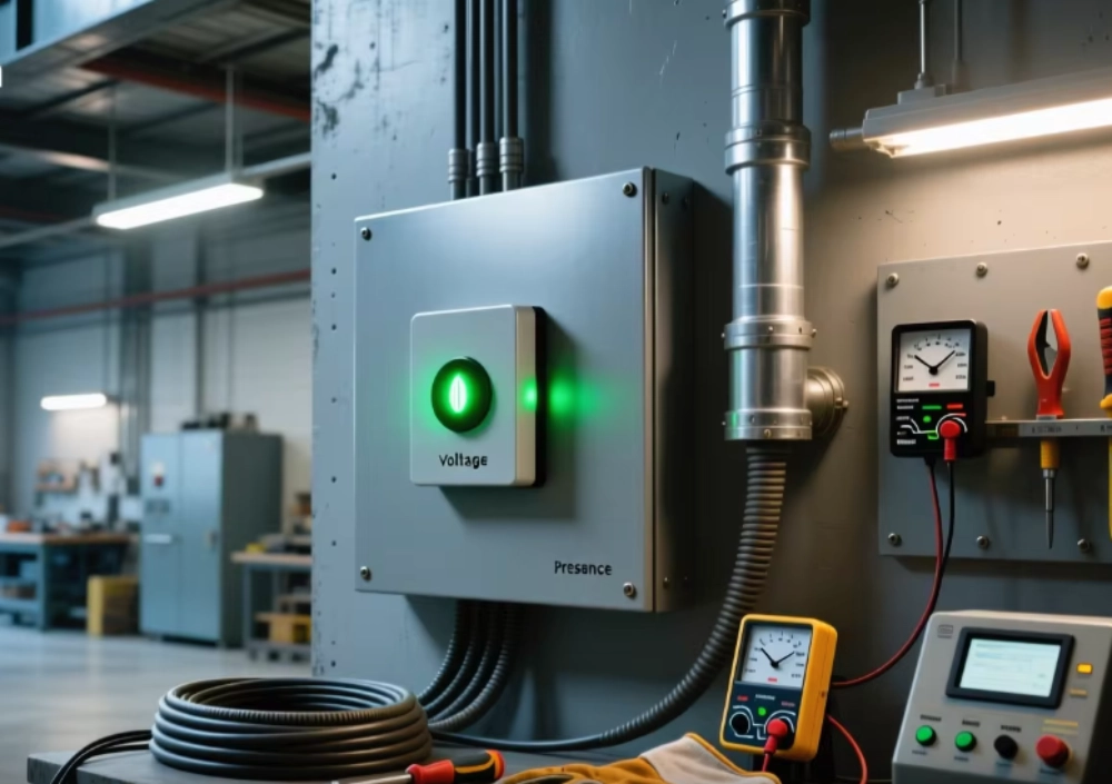
VDIS Voltage Output supports reliable voltage status detection in MV switchgear through capacitive coupling and signal processing.
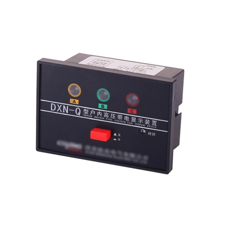
What Is VDIS Voltage Output?
VDIS Voltage Output defines the electrical signal produced by a voltage detection system. It helps operators identify voltage presence within medium-voltage switchgear. The output normally represents an electrical state, rather than the full primary voltage. Engineers evaluate the coupling interface, sensing circuit, and output terminals together. This approach supports reliable phase detection during commissioning and operation. Proper selection also requires attention to rated voltage and system frequency. A mismatch can create weak or misleading indication signals. Modern switchgear designs often connect detection outputs with local indicators. Some systems also provide interfaces for monitoring or interlocking logic. The final signal depends on the complete detection chain, not one component alone.
How Does VDIS Generate A Voltage Output Signal?
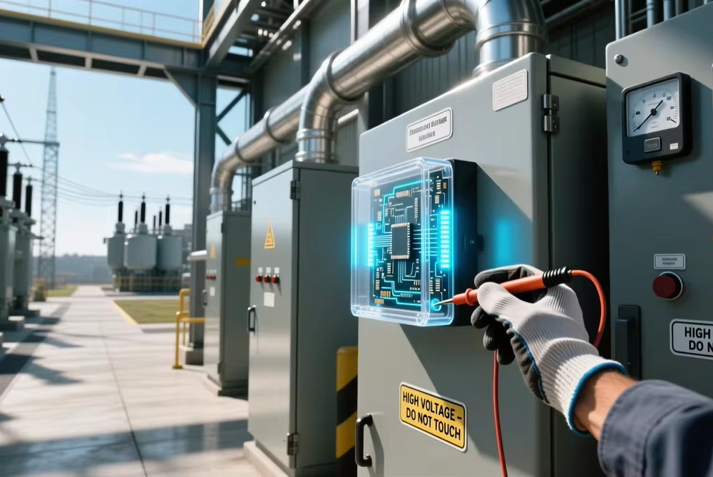
A VDIS starts with capacitive coupling from an energized primary conductor. The coupling interface transfers a controlled sensing signal into the detection circuit. Engineers design this interface around voltage class, frequency, insulation, and capacitance. The sensing circuit then conditions the received signal for reliable indication. Signal conditioning can include filtering, limiting, or threshold comparison. These functions protect sensitive detection components from excessive electrical stress. The resulting signal represents the detected phase condition at the interface. Output terminals then provide a defined signal for connected indication equipment. Engineers should never assume that every VDIS uses the same signal level. Interface specifications determine the acceptable electrical range and connection method. Correct matching therefore remains essential during equipment integration.
What Does The Output Signal Represent?
The output usually represents voltage presence rather than an exact primary voltage measurement. A live indication confirms sufficient electrical potential at the sensing interface. A dead indication means the signal remains below the defined detection threshold. Some systems provide separate signals for different phases. Others combine phase information through a dedicated indication module. Engineers must review the electrical interface specification before wiring. The output can also support status transmission to another control device. Such transmission requires compatible signal levels and suitable isolation. A detection output should not automatically serve as a protection input. Protection systems require their own accuracy, response, insulation, and reliability requirements. Clear functional separation prevents incorrect assumptions during system design.
Which Electrical Parameters Affect Detection Performance?
Several electrical parameters influence signal stability and detection reliability. Rated system voltage determines the expected sensing range. Frequency affects capacitive reactance and the resulting coupled signal. Phase arrangement also matters because each phase requires correct identification. Coupling capacitance influences the magnitude of the transferred sensing signal. Cable length can introduce additional capacitance and signal attenuation. Input impedance affects the electrical loading seen by the coupling interface. Temperature can change component characteristics within electronic detection circuits. Humidity and contamination can also affect insulation behavior around interfaces. Engineers should evaluate these conditions against specified operating limits. Reliable detection requires compatibility across the complete sensing path.
| Parameter | Function | Engineering Check |
|---|---|---|
| Rated voltage | Defines the sensing application | Switchgear nameplate |
| Frequency | Affects capacitive sensing behavior | System specification |
| Phase arrangement | Maintains correct channel identification | Electrical schematic |
| Coupling capacitance | Influences transferred signal level | Interface specification |
| Input impedance | Affects circuit loading | Technical documentation |
| Operating temperature | Influences component stability | Environmental specification |
These parameters should be reviewed as one integrated specification. Choosing components from voltage rating alone can create interface problems. Engineers should request complete electrical drawings and terminal definitions. Factory testing can verify the selected configuration under controlled conditions. Sample approval can also confirm mechanical and electrical compatibility. This process reduces field modifications and commissioning delays. It also creates a clearer technical record for replacement orders. Proper documentation helps maintenance teams identify the correct components later. Consistent specifications therefore support both procurement and long-term reliability.
VDIS Voltage Output In MV Switchgear Applications
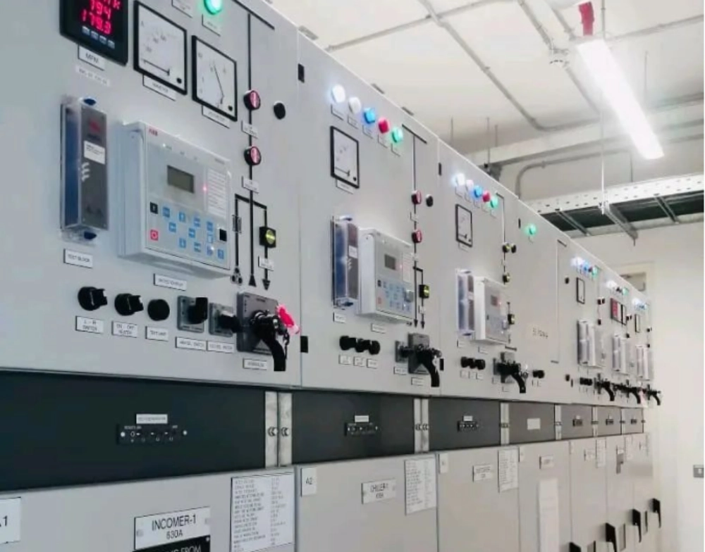
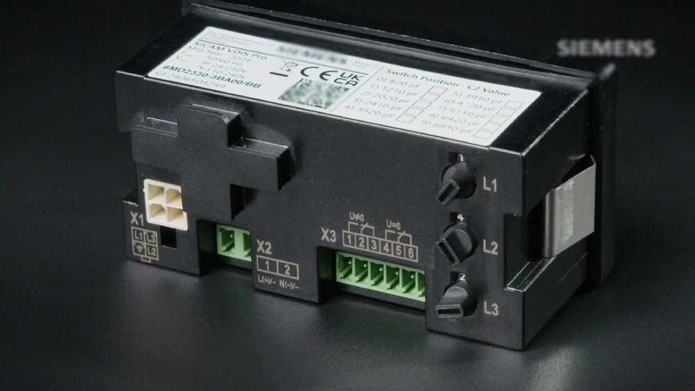
VDIS Voltage Output becomes useful when medium-voltage switchgear requires voltage-status information. A typical panel may contain three phase conductors and three sensing interfaces. Each phase routes through its designated capacitive coupling path. The detection module receives these signals and determines the voltage state. Local indicators can display the presence condition for operating personnel. Remote outputs may transfer status information to supervisory control circuits. Interlocking logic can use compatible status signals when the design permits. Engineers must verify isolation between detection circuits and control circuits. Terminal arrangements should also match the approved switchgear wiring diagram. Integration becomes safer when electrical and mechanical interfaces receive equal attention.
How Should A Three-Phase Output Arrangement Be Checked?
A three-phase arrangement normally assigns one detection channel to each phase. The channels should retain consistent phase identification throughout the circuit. This prevents a correct voltage condition from appearing on the wrong indicator. The table below summarizes typical relationships between key components.
| Component | Primary Function | Key Verification |
|---|---|---|
| Primary conductor | Provides the sensed voltage source | Rated voltage |
| Capacitive interface | Transfers the sensing signal | Interface compatibility |
| Detection circuit | Processes the coupled signal | Input range |
| Phase indicator | Displays voltage presence | Phase identification |
| Output terminal | Transfers status information | Wiring and isolation |
This arrangement shows why the signal cannot be evaluated independently. Every stage affects the final detection state. A wiring error at one phase can create an apparently valid indication elsewhere. Engineers should verify phase continuity before applying operating voltage. Terminal labels should match the approved schematic and panel markings. Measurements should follow the specified commissioning procedure. The output interface also needs protection from accidental overvoltage. Proper circuit segregation reduces interference and limits fault propagation. These checks provide a stronger basis for dependable commissioning.
What Should Engineers Check During Verification?
Engineers should begin with the switchgear nameplate and approved electrical drawings. The rated voltage and frequency must match the selected detection interface. Each phase connection should follow its assigned terminal designation. The coupling interface should have suitable insulation and mechanical clearance. A controlled commissioning sequence should include these checks:
- Confirm the switchgear rated voltage and operating frequency.
- Verify phase sequence and detection channel assignment.
- Check every coupling interface against the approved schematic.
- Inspect terminal tightness, insulation, and conductor routing.
- Verify output polarity and signal characteristics.
- Check indicator operation for each phase.
- Record test conditions and measured results.
A controlled sequence helps separate wiring problems from component problems. Engineers should test each phase separately when the design permits. They should compare measured results with specified output limits. Unexplained differences require investigation before normal operation begins. Field testing should follow all required switchgear safety procedures. Test records should include instruments, operating conditions, and measured values. Such records help maintenance teams diagnose future indication changes. Consistent documentation also improves traceability during equipment service.
What Problems Can Cause An Incorrect Output?
An incorrect output can result from several faults within the detection chain. Incorrect phase wiring remains a common commissioning concern. A mismatched voltage class can also produce an unsuitable sensing signal. Loose terminals may create intermittent indications during vibration or thermal cycling. Damaged coupling components can reduce signal transfer from the primary conductor. Excessive cable capacitance may alter expected circuit behavior. Moisture and contamination can influence insulation conditions around sensing interfaces. Incorrect threshold settings can also cause premature or delayed status changes. Engineers should compare symptoms across all three phases before replacing components. If one phase differs sharply, its local wiring deserves close inspection. A systematic check prevents unnecessary replacement of functional equipment.
How Does VDIS Voltage Output Support Switchgear Safety?
VDIS Voltage Output can support safer operating decisions by providing voltage-status information. Operators can use local indications before approved switching procedures. Control systems may also receive compatible status information through designated interfaces. However, indication does not replace required isolation and verification procedures. De-energized status should always follow the applicable site safety process. Engineers must also distinguish indication from measurement accuracy. A presence detector normally identifies whether voltage exceeds a defined threshold. It does not necessarily provide a calibrated primary voltage value. Interlocking functions require additional evaluation of logic and circuit isolation. Designers should assign each signal a clearly defined safety role. This prevents a simple status output from carrying an unsuitable protection function.
What Does A Real Switchgear Commissioning Case Show?
A field commissioning case illustrates how a small wiring issue can affect the complete system. A medium-voltage switchgear panel showed inconsistent phase indication during commissioning. Two phases produced expected live status, while the third remained inactive. Engineers first confirmed the panel voltage and system frequency. They then compared all three coupling interfaces with the approved schematic. The third channel used the correct component but had an incorrect terminal assignment. After correcting the connection, the phase indicator responded normally. The team repeated the phase checks under specified test conditions. This case shows why component replacement should not be the first response. A correct component can still produce an incorrect result after poor integration. The same diagnostic logic applies to many switchgear detection installations.
How Can Specialized VDIS Configurations Affect Installation?
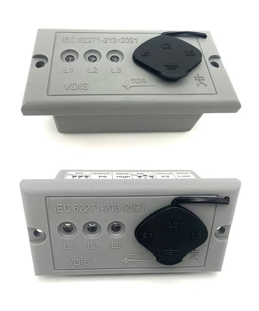
Specialized configurations can require different mechanical and electrical interface requirements. Panel dimensions directly affect mounting positions and front-panel alignment. Electrical interfaces can also differ between compact and larger detection assemblies. For example, a 88x28mm switchgear voltage indicator vpis OEM/ODM configuration may require a specific panel opening. Engineers should confirm display dimensions before approving enclosure machining. They should also verify the electrical interface and phase arrangement separately. Physical compatibility does not prove electrical compatibility. A compact indicator may fit correctly while requiring another signal interface. Production drawings should therefore include both mechanical and electrical details. Sample approval can confirm display position and terminal orientation. These checks help prevent avoidable changes during cabinet assembly.
How Can Engineers Maintain Reliable Detection Performance?
Reliable performance depends on correct selection, installation, testing, and maintenance. Engineers should periodically inspect terminals for looseness and visible deterioration. Cabinet cleanliness also matters because contamination can affect insulation around sensing interfaces. Temperature conditions should remain within the specified equipment range. Unusual indication changes deserve investigation rather than immediate reset. Maintenance teams should compare present behavior with commissioning records. Phase-to-phase comparison can help identify localized degradat
FAQ
What Is VDIS Voltage Output Used For?
VDIS Voltage Output primarily communicates voltage presence within medium-voltage switchgear. The signal can support local indication or compatible monitoring circuits. It does not automatically represent the exact primary voltage value. Capacitive coupling transfers a controlled sensing signal from the energized conductor. The detection circuit evaluates that signal against defined operating conditions. Engineers must check the interface specification before connecting another device. Compatibility includes electrical range, terminal arrangement, isolation, and phase assignment. Safety procedures remain necessary when personnel work on switchgear. Voltage indication cannot replace approved isolation and verification practices. Proper application depends on the complete sensing architecture and equipment specification.
Does VDIS Output Provide The Actual Primary Voltage?
Usually, the output indicates voltage presence rather than delivering the full primary voltage. Capacitive sensing reduces the electrical level before the signal reaches detection electronics. The resulting signal allows the system to determine whether voltage exceeds its threshold. Engineers should not treat the indicator signal as a calibrated primary measurement. Exact behavior depends on the sensing interface and connected detection electronics. Some systems may provide additional processing for downstream status transmission. The output specification determines what that signal actually represents. Designers should review accuracy, threshold, isolation, and interface requirements separately. This distinction prevents incorrect connections to measurement or protection equipment. Any required voltage measurement should use equipment designed for that purpose.
How Can Engineers Check VDIS Output During Commissioning?
Engineers should verify rated voltage, frequency, phase arrangement, and interface compatibility first. Next, they should compare every terminal with the approved switchgear schematic. Physical inspection should confirm secure connections and suitable insulation conditions. Each phase should then receive the specified commissioning checks. Measured results should remain within the equipment's stated operating range. An abnormal phase should trigger a wiring and interface investigation. Engineers should compare that channel with correctly operating phases. They should avoid replacing components before confirming the complete signal path. Test instruments must also suit the circuit and required measurement conditions. Finally, teams should record test results, conditions, and corrective actions. Clear records make later troubleshooting faster and support consistent maintenance.