
What VDIS Specifications Matter For Switchgear?
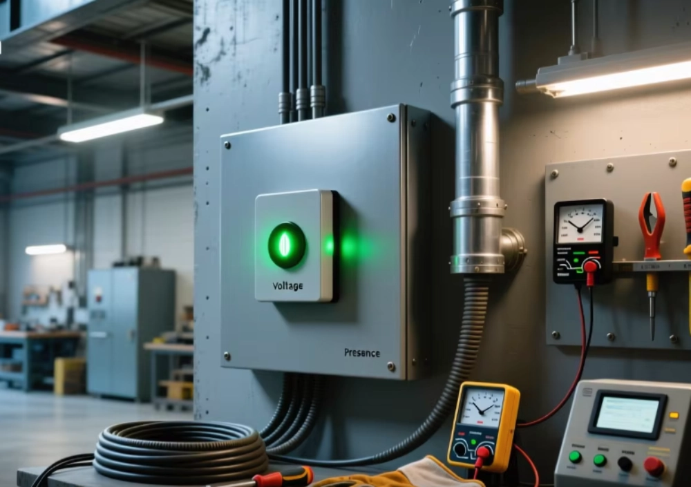
VDIS Technical Specification covers voltage detection, insulation, wiring, and environmental requirements for reliable switchgear systems.
VDIS Technical Specification And Its Role In Switchgear
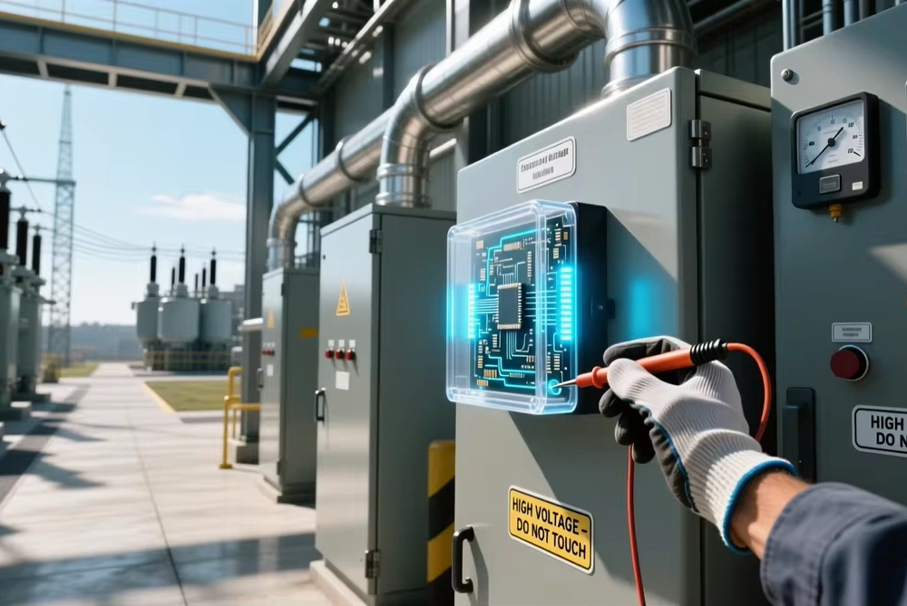
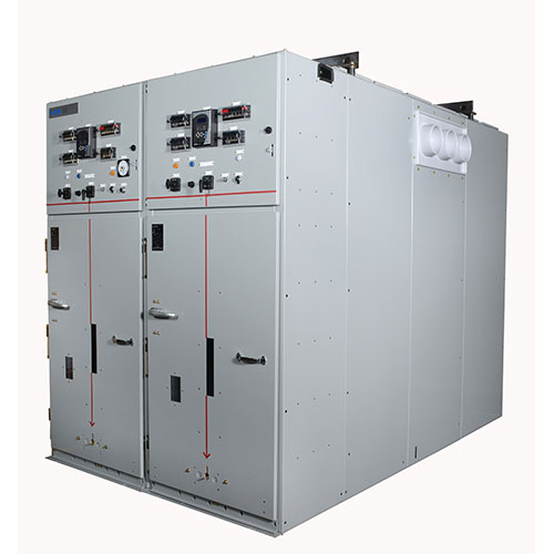
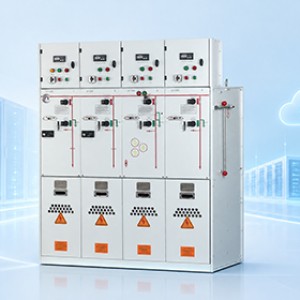
A VDIS Technical Specification defines the electrical and mechanical parameters for voltage indication systems. These parameters affect detection reliability inside medium voltage switchgear. A complete specification must address more than nominal voltage. Engineers should also check coupling interfaces, insulation, frequency, wiring, and environmental limits. IEC 62271-213:2021 covers voltage detecting and indicating systems for indoor and outdoor high-voltage equipment. The standard includes a coupling system for each phase. Such systems connect the indicator to live parts through suitable technologies. Therefore, specification review should start with the complete switchgear design. Engineers must compare the indicator with the primary circuit and cabinet arrangement. This approach reduces interface errors during production and commissioning. It also supports consistent indication across different switchgear configurations.
Voltage Detection Requirements For Medium Voltage Switchgear
Voltage detection begins with the electrical characteristics of the primary circuit. Engineers need the system voltage, frequency, phase arrangement, and grounding configuration. The detection interface must also match the intended switchgear construction. Capacitive coupling commonly transfers a small signal from the energized conductor. The indicator then processes that signal and presents a visible voltage status. Detection should remain stable under normal operating conditions. Excessive signal variation can create unclear or inconsistent indications. Engineers should also verify the intended connection between each phase and its detection channel. Incorrect phase wiring can create misleading status information. Such errors become especially serious during maintenance or switching operations. A proper specification therefore connects detection performance with cabinet wiring and primary circuit design.
Rated Voltage And Frequency Compatibility
Rated voltage provides one of the first selection boundaries for a voltage indicator. A 12 kV switchgear system cannot automatically accept every indicator marketed for medium voltage use. Engineers must check the actual rated voltage range and interface design. Frequency also matters because the coupling circuit responds to electrical conditions. Many industrial systems operate at 50 Hz or 60 Hz. The selected component should match the intended network frequency. Engineers should also verify whether the specified voltage represents system voltage or another rating parameter. Confusing these values can produce an incorrect selection. The following table shows practical screening points for a medium voltage project.
| Specification | Typical Project Question | Selection Concern |
|---|---|---|
| Rated voltage | What is the switchgear system voltage? | Indicator range must match the primary system |
| Frequency | Is the network 50 Hz or 60 Hz? | Interface characteristics must suit the network |
| Phase arrangement | How many detection channels are required? | Each phase needs correct connection |
| Installation type | Is the cabinet indoor or outdoor? | Environmental limits must match the site |
Insulation Level And Dielectric Performance
Insulation performance remains critical because the indicator connects electrically to the primary circuit. Engineers should review rated insulation voltage and applicable withstand requirements. Power-frequency withstand capability matters during factory and field testing. Lightning impulse withstand capability also affects insulation coordination. These values should align with the switchgear insulation system. Physical clearances around terminals and coupling components require equal attention. Conductive contamination can reduce effective insulation margins inside compact cabinets. Dust, moisture, and condensation may create additional surface leakage paths. Cabinet construction therefore influences the long-term electrical environment. Engineers should review mounting location before approving the indicator. Components placed too close to grounded metalwork can create unnecessary dielectric stress. Correct insulation coordination supports stable operation and safer maintenance conditions.
VDIS Technical Specification For Detection And Indication
A detailed VDIS Technical Specification should define how voltage presence appears to the operator. Indication may use visual elements for each phase. The design should make energized and non-energized conditions easy to distinguish. Engineers should verify the indicator's intended threshold and operating behavior. They should also confirm the testing interface where applicable. A phase comparator can provide additional confirmation when two energized circuits require comparison. IEC 62271-215:2021 specifically addresses phase comparators used with VDIS systems. It supports phase relationship checks before coupling energized parts. The indicator should not be treated as a general voltage measurement instrument. Its purpose focuses on voltage condition indication. Clear functional boundaries help prevent incorrect operating assumptions during maintenance.
Capacitive Interface And Coupling Requirements
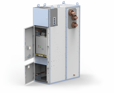
The coupling interface transfers a controlled signal from the primary circuit to the indication system. IEC 62271-213 includes a coupling system for each phase. The coupling technology may use capacitive, resistive, or other suitable principles. Engineers must confirm compatibility between the coupling element and the indicator. They should also verify the physical interface and connection arrangement. A mismatched coupling interface can produce weak or unstable indication. Signal routing deserves similar attention inside a metal-enclosed cabinet. Long or poorly arranged connections may complicate installation and testing. Engineers should document each phase connection before assembly. Factory technicians can then verify the wiring against the approved drawing. This process reduces accidental phase interchange and incomplete connections. It also makes later maintenance more straightforward.
Phase Arrangement And Wiring Configuration
Phase wiring directly affects whether the displayed voltage condition represents the correct circuit. Each detection channel should correspond with its intended phase. Terminal identification should remain consistent between electrical drawings and physical hardware. Engineers should avoid ambiguous labels inside crowded switchgear compartments. Wiring should also maintain suitable separation from unrelated control circuits. Shielding and grounding requirements depend on the selected system architecture. Mechanical protection matters where wires pass through sheet metal openings. Sharp edges can damage insulation during vibration or service work. The following table provides a practical wiring verification framework.
| Check Item | Verification Method | Typical Risk |
|---|---|---|
| Phase identification | Compare terminals with approved drawings | Incorrect phase indication |
| Connection security | Inspect and torque connections as specified | Intermittent signal |
| Cable routing | Check routing against cabinet layout | Mechanical or electrical interference |
| Terminal insulation | Inspect spacing and insulation condition | Reduced dielectric margin |
| Functional test | Verify each phase indication | Undetected wiring error |
Environmental And Mechanical Requirements
Electrical specifications alone cannot guarantee reliable operation inside a switchgear cabinet. Temperature can affect electronic components, connection materials, and indication stability. Humidity creates additional concerns when cabinets experience condensation. Outdoor equipment may also face wider temperature variations and contamination. Engineers should therefore compare operating limits with the actual installation environment. Mechanical vibration deserves attention in transportable or frequently operated equipment. Mounting dimensions must fit the designated panel opening and support structure. Terminal orientation can also affect wiring access and maintenance. A compact indicator may still require sufficient rear clearance for connections. Engineers should confirm mounting holes before final cabinet fabrication. They should also inspect enclosure protection requirements for the intended installation location. These checks should form part of the VDIS Technical Specification review to prevent avoidable modification work during final assembly.
Electrical Safety And Interlocking Considerations
Voltage indication contributes to operational awareness, but it does not replace established electrical safety procedures. Operators should use the indicator as one part of a controlled switching process. Earthing operations require correct coordination with the switchgear design. Door interlocks may also depend on the intended operating sequence. Engineers should confirm that the indicator location remains visible during normal operation. A hidden indicator provides limited practical value during inspection. The display should also remain identifiable under the cabinet's expected lighting conditions. For example, an 88x28mm switchgear voltage indicator vpis OEM/ODM configuration may require a specific panel cutout. That dimension should be checked against the cabinet drawing before production. Mechanical fit and electrical compatibility should receive equal attention. Proper coordination helps prevent installation delays and unsafe assumptions during commissioning.
Real 12 kV Switchgear Application And Specification Review
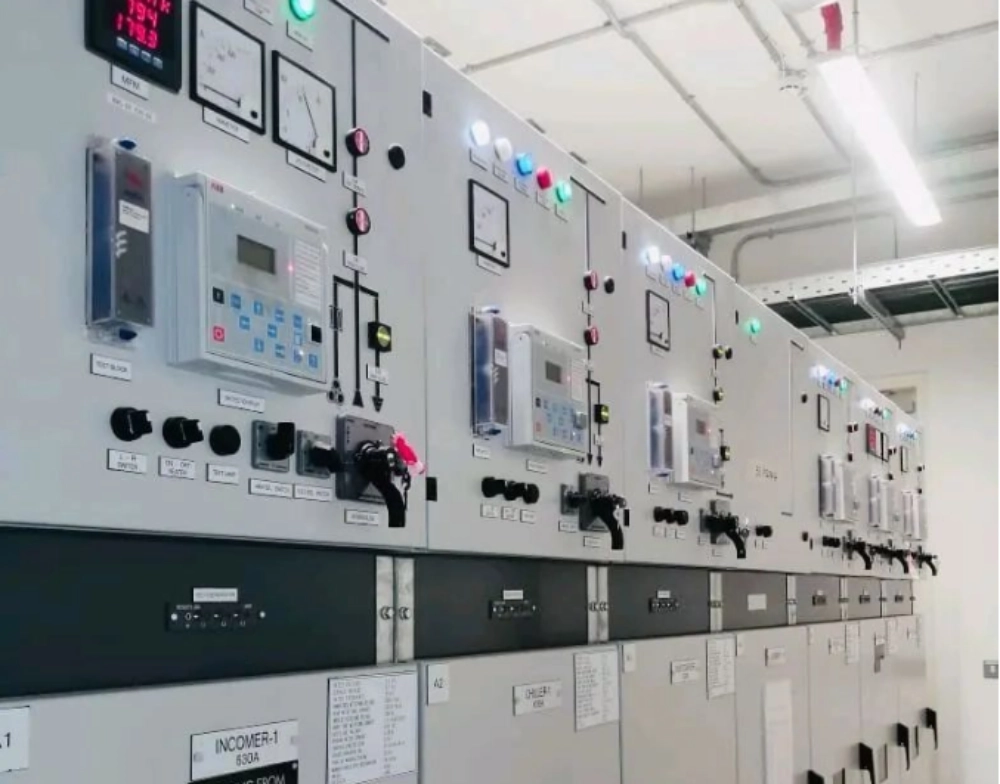
A practical 12 kV indoor switchgear project shows why complete specification matching matters. The cabinet uses a three-phase medium voltage primary circuit with a standard industrial frequency. Engineers first confirm the system voltage and required indication arrangement. They then verify the coupling interface for each phase. Next, the team checks panel cutout dimensions and rear wiring space. The insulation requirements receive separate review against the switchgear design. Environmental conditions also receive attention because the cabinet operates in a controlled electrical room. During factory assembly, technicians verify phase wiring against the approved schematic. Each indication channel then receives a functional check. This process identifies wiring errors before shipment. In another configuration, a DXN8D 12 voltage presence indicating system may require different mounting and interface checks. The key lesson remains consistent: component selection must follow the complete cabinet design.
Installation And Maintenance Verification
Installation quality determines whether the specified electrical performance remains reliable in service. Technicians should inspect mounting position before connecting the detection circuit. Wiring should follow the approved schematic and terminal identification. Connections should receive the specified tightening treatment during assembly. After installation, each phase should receive a functional verification. Technicians should record abnormal indication behavior rather than immediately replacing components. Loose terminals, incorrect phase connections, and damaged coupling elements can create similar symptoms. Maintenance teams should also inspect the cabinet environment during scheduled service. Dust and moisture may indicate wider enclosure or ventilation problems. Replacement components should match the approved electrical and mechanical parameters. Keeping installation records improves troubleshooting during later maintenance. Consistent verification also helps maintain the original design intent and confirms the approved VDIS Technical Specification remains aligned with the installed system.
Specification Coordination For Reliable Switchgear Integration
Reliable integration depends on coordination between electrical, mechanical, and environmental requirements. Engineers should avoid selecting an indicator from voltage rating alone. The primary circuit, coupling interface, mounting arrangement, and wiring plan must work together. IEC 62271-200:2021 applies to metal-enclosed AC switchgear above 1 kV and up to 52 kV. Its scope includes indoor and outdoor assemblies with service frequencies up to 60 Hz. This broader switchgear context matters when integrating voltage indication equipment. The final specification should identify every interface that affects cabinet performance. Procurement teams can then compare technically equivalent components more effectively. Production teams can use the same information during assembly inspection. Service teams can also reference the specification during replacement work. A coordinated specification therefore supports reliability from design through maintenance.
Key Specification Checklist For Switchgear Projects
A practical selection process should convert technical requirements into measurable checkpoints. Engineers can use the following list before approving a voltage indication system:
- Confirm the switchgear rated voltage and frequency.
- Verify the required phase detection arrangement.
- Check the coupling interface for every phase.
- Review insulation and dielectric requirements.
- Confirm panel dimensions and mounting positions.
- Verify terminal identification and wiring routes.
- Check operating temperature and humidity limits.
- Review environmental and enclosure conditions.
- Confirm testing and commissioning procedures.
- Record approved electrical and mechanical parameters.
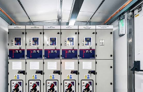
This checklist works best when engineers compare every value with the cabinet design. Procurement teams should avoid accepting incomplete technical data. Manufacturing teams should also retain the approved specification with production drawings. Any design change should trigger a compatibility review. Such control prevents small interface changes from creating larger commissioning problems. The same process also improves traceability for future replacement requirements.