
How Do You Check VPIS Operating Temperature Limits?
Check VPIS Operating Temperature against cabinet conditions, cold starts, storage limits, condensation, and model-specific test evidence.
Start With the Exact Product Rating
VPIS Operating Temperature defines the ambient conditions under which a specified indicator can perform its documented functions. There is no single range you can apply to every model. For example, a project may specify a device rated from −25°C to +50°C. Treat that range as an illustrative requirement until the supplier confirms the exact model. Start your own review with the exact model, hardware version, and technical document revision. Then compare the declared limits with the conditions at the intended mounting location. Include cold starts, normal operation, and the hottest expected cabinet condition in that comparison.
Where Should You Measure VPIS Operating Temperature?
Use the manufacturer's definition of ambient temperature to establish the measurement location. Room temperature alone can miss heat inside the instrument compartment. Nearby power supplies, heaters, and other components can raise the local air temperature. Collect representative readings near the indicator without obstructing ventilation or approaching hazardous parts. A qualified team should plan sensor placement under the approved cabinet procedure. Record enclosure temperature and room temperature together during the relevant operating conditions. Keep the cabinet doors in their normal service position. That gives the designer a record of the conditions the installed device actually experiences.
What Does a Temperature Comparison Tell You?
Consider an illustrative indicator with a declared upper ambient limit of +50°C. A room reading of +40°C and a local rise of 12°C produce a +52°C installation condition. That exceeds the example rating even though the room remains cooler. Use measured or justified cabinet data for the local rise. Compare the lowest expected temperature with the lower limit in the same way. Include measurement uncertainty when judging a narrow margin. If the conditions exceed either boundary, review the cabinet thermal design or select a suitably qualified configuration. Obtain approval for the final combination before procurement.
Example temperature review for a hypothetical −25°C to +50°C device
| Condition | Local ambient | Assessment |
|---|---|---|
| Warm room plus internal heating | +40°C + 12°C = +52°C | Exceeds the example upper limit |
| Cold start after an unheated shutdown | −30°C | Below the example lower limit |
| Normal service | +35°C | Within the example range, subject to other declared conditions |
How Do Storage Limits and Cold Starts Differ?
An allowed storage range describes conditions while the device remains out of service under specified handling conditions. The operating range concerns the functions the manufacturer qualifies during use. Record both limits separately in the procurement specification. After a cold shutdown, the indicator can begin service near the overnight cabinet temperature. A warmer room later in the day does little to establish that starting condition. Ask whether the declared operating range includes starting at its lower boundary. For equipment arriving from cold storage, follow the supplier's acclimatization instructions and inspect for condensation before commissioning.
Why Does Condensation Need a Separate Check?
Moisture can condense when a surface falls below the surrounding air's dew point. This can happen during warming after a cold period, even within a stated temperature range. Record the humidity requirements and any restriction on condensation alongside the thermal limits. Review cabinet sealing, ventilation, and humidity control as part of the complete installation. Heating can help maintain suitable conditions, but its location can also raise the indicator's local ambient. Check the heater arrangement and control settings together. Inspect the enclosure for water ingress during maintenance and address the source through the approved cabinet procedure.
What Can You Confirm From the Product Pages?
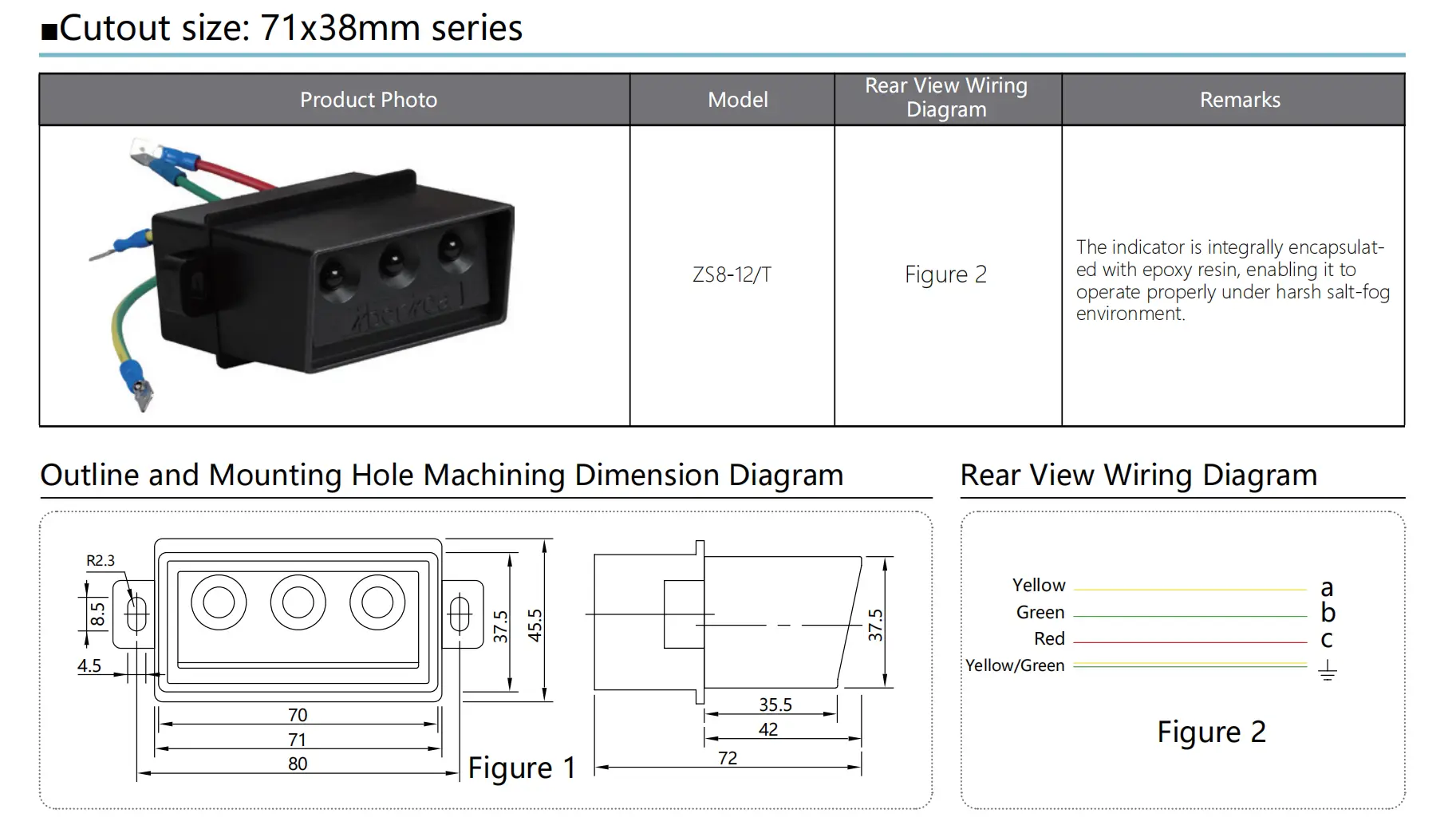
The 71×38 mm VPIS product provides an example for reviewing a particular installation. Its public parameter image identifies the ZS8-12/T model and its encapsulated construction. Request its model-specific operating and storage limits with the quotation. For an 88×28 mm VPIS product, obtain the corresponding documents before comparing suitability. Keep the specified cutout, sensing interface, voltage range, and environmental limits in the same review. A mounting dimension or encapsulation description provides only part of that selection information.
Which Test Evidence Supports Temperature Suitability?
Ask for evidence covering the quoted model, its declared temperature limits, and the relevant operating functions. The review should identify the test conditions, sample configuration, acceptance criteria, and results. Check whether testing addresses indication performance after temperature exposure and during the specified conditions. Where the product has additional outputs, include their declared functions in the review. Confirm that the sensing arrangement and installation configuration match the intended application. Record any differences for engineering assessment. A VPIS Operating Temperature statement should identify the configuration and functions its supporting documents cover.
Frequently Asked Questions
Can I use −25°C to +50°C as the default range?
Use the range declared for the exact product and installation. The −25°C to +50°C figure appears in some manufacturer manuals for specified equipment. Other designs can have different limits and qualification conditions. Include the full model code, document revision, operating range, and storage range in your comparison. Check whether the quoted limits apply to local ambient air at the indicator. Ask for clarification if the supplier gives a series-level statement without identifying the proposed version. Confirm the complete installation against its environmental requirements before accepting the order.
Does a higher temperature rating make a replacement compatible?
Temperature suitability addresses one part of replacement selection. Compare the sensing interface, nominal voltage range, frequency, phase connections, and mounting arrangement as well. If the existing system uses additional outputs, verify their functions and ratings against the cabinet schematic. A wider thermal range can help with demanding ambient conditions. Engineering review must also address the remaining configuration. Request the replacement's technical documents and compare them with the installed equipment records. Keep the accepted model and any drawing changes together so maintenance teams can identify the approved arrangement.
What should I do if the indication changes in hot weather?
Record the time, local ambient, operating load, and the affected phase indication through the approved maintenance process. Compare those observations with the product's declared limits and previous service records. Qualified staff should investigate the sensing connections, indicator condition, and any relevant supply circuit using approved methods. An intermittent display requires investigation before anyone relies on it for an operating decision. Follow the site's isolation and absence of voltage verification procedure for access. Retain the findings with the cabinet record and review thermal conditions if measurements show an excursion.