
How Does a DSN-DM Electromagnetic Lock Control Access?
Match a DSN-DM Electromagnetic Lock to your switchgear. Check phase signals, sensor compatibility, release conditions, and door alignment.
Start With the Indication and Interlock Circuit
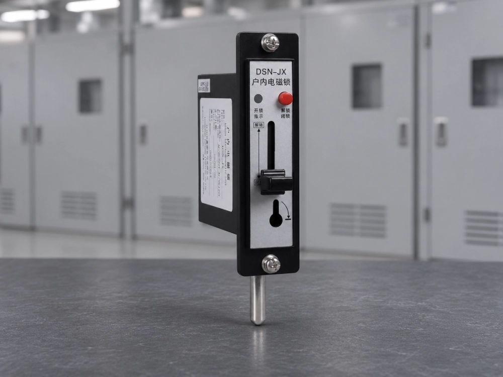
A DSN-DM Electromagnetic Lock combines door locking with voltage indication in a coordinated switchgear arrangement. Selection starts with the sensing circuit, auxiliary supply, and cabinet access sequence. Identify which compartment the sensors monitor and which door the bolt restrains. Then check how the controller turns those inputs into release permission. Record the exact lock version alongside its wiring diagram. That information helps purchasing and engineering review the same configuration. For replacement work, include the original sensor details and cabinet schematic with the enquiry.
How the DSN-DM Electromagnetic Lock Uses Phase Signals
Consider a cabinet whose release circuit requires all monitored phases to indicate absence of voltage. With phase A indicating voltage, the controller should withhold release even if phases B and C appear clear. After the required conditions become valid, the release circuit can permit coil actuation. The operator then moves the handle to withdraw the bolt according to the operating instructions. Other cabinet interlocks may still govern access. During testing, follow this sequence from sensor input through indication, permission, and bolt movement. A disagreement at one stage identifies where the team should investigate next.
Which Signals Should Operators Check?
Read the labels for phase indication, auxiliary power, and release permission before operating the handle. Each signal has a different role in the cabinet sequence. A power lamp reports the condition assigned to its supply circuit. The release lamp reports the condition assigned to the unlocking circuit. Check the actual bolt movement and door restraint during the approved functional test. For access, follow the site's isolation and absence of voltage verification procedure. A dark phase display alone provides insufficient evidence for authorizing entry. Include sensor and indication checks in the documented access procedure.
| Observation | Required check |
|---|---|
| Phase indication present | Confirm the corresponding monitored circuit and expected restraint. |
| Phase display dark | Check sensing integrity and follow the approved voltage verification procedure. |
| Release indication present | Check the specified bolt action and any fitted feedback. |
| Auxiliary supply interrupted | Verify the documented response from each starting position. |
Which Model and Wiring Version Should You Order?
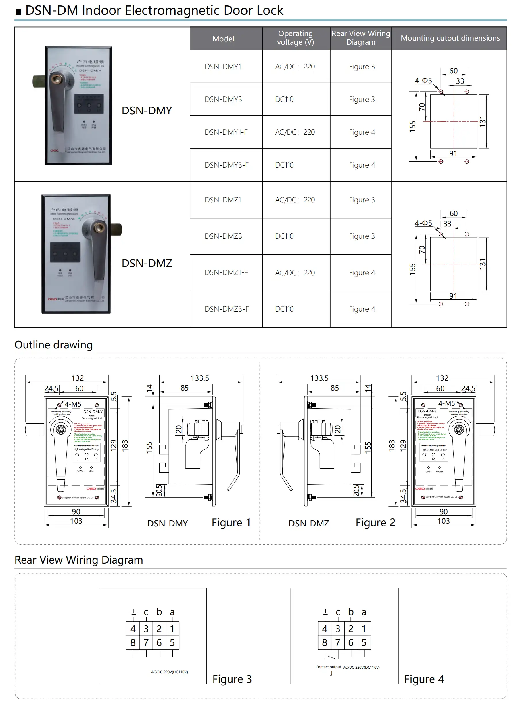
The DSN-DM product drawing lists Y and Z configurations with different supply and wiring options. Its Y front view shows the bolt projecting left, while Z shows it projecting right. Match that view to your cabinet sketch before choosing a version. The table identifies Figure 3 for standard versions and Figure 4 for -F versions. Figure 4 includes a contact output. Confirm its rating and switching function against the project circuit before using that output. Include the full suffix and approved diagram reference in the purchase specification.
Model and circuit options shown in the official drawing
| Models | Operating supply options | Rear wiring reference |
|---|---|---|
| DSN-DMY1 / DSN-DMZ1 | 220 V AC or DC | Figure 3 |
| DSN-DMY3 / DSN-DMZ3 | 110 V DC | Figure 3 |
| DSN-DMY1-F / DSN-DMZ1-F | 220 V AC or DC | Figure 4, with contact output |
| DSN-DMY3-F / DSN-DMZ3-F | 110 V DC | Figure 4, with contact output |
Why Must the Sensor Interface Match?
The sensing interface connects the monitored circuit to the indication and interlock functions. Confirm the sensor type and signal requirements with the lock's system documentation. Check the phase assignments and the intended reference connection against the cabinet schematic. An incorrect connection can prevent the display from representing the intended circuit. For a retrofit, identify the existing sensors before accepting the replacement lock. Ask the supplier to confirm compatibility for that specific combination. During commissioning, test each input through the approved method and record the corresponding indication and restraint. Keep that interface record with the cabinet drawings.
How Should You Check the Door Fit?
The official drawing shows a 91 × 131 mm panel opening and four 5 mm fixing holes. Check their offsets against the dimensioned pattern before machining. Measure rear clearance and bolt position from the mounting face. Compare the proposed drawing with the door's actual panel thickness. Check where the bolt engages the receiving bracket when the door closes normally. Include hinge play and door gap in that assessment. During an approved fit check, observe the handle through its full travel. Verify that adjacent equipment leaves enough operating space. Confirm that the bolt clears its receiving surface during release and engages within the cabinet's specified limits. Record the final position for future replacements.
How Do You Test the DSN-DM Electromagnetic Lock?
Create a test sheet from the approved circuit and operating instructions. List the starting position, simulated input condition, expected indication, and expected mechanical response. Include each phase input using the manufacturer's approved test method. Check permitted and inhibited release states as separate cases. Where the procedure requires it, include auxiliary power interruption and restoration. Observe the bolt and any feedback contact alongside the display. Compare the results with the cabinet's required access sequence. Investigate any disagreement before acceptance, then retain the completed test sheet with the commissioning documents.
Can Another DSN Lock Replace the Original?
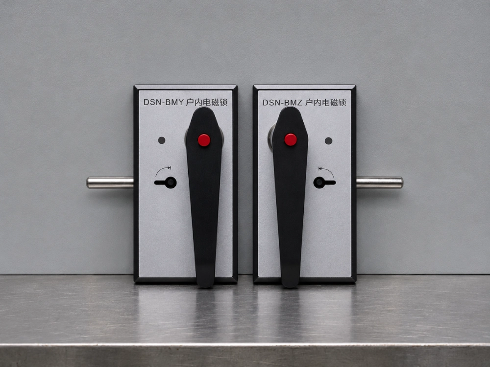
A replacement review must cover the indication and sensing functions as well as the mechanical fit. The DSN-BM handle lock offers another configuration for evaluating cabinet interlocking requirements. Compare its documented functions with the original cabinet design. Identify where the existing system obtains phase signals and generates release permission. Check whether the proposed arrangement preserves every required input, output, and access condition. Include terminal changes and indication changes in engineering review. Keep the accepted schematic revision with the replacement order and maintenance record.
Frequently Asked Questions
Can I open the door when all phase lights are dark?
Follow the site's approved isolation and absence of voltage verification procedure before accessing the compartment. Dark indicators can result from several conditions, including missing sensing signals or a display fault. Identify the monitored circuit and verify the indication system through the approved procedure. Check auxiliary power and release permission according to the cabinet schematic. A qualified team should resolve unexpected indications before authorizing entry. Record the condition and the checks completed in the maintenance log. The cabinet instructions should define the complete access sequence for the installed equipment.
What should I check if the lock refuses to release?
Start by recording the phase lights, power lamp, release lamp, and bolt position. If a phase indicates voltage, compare that state with the monitored circuit through the approved verification procedure. With a dark display and missing power indication, investigate the auxiliary supply and sensing integrity before attempting access. If release permission appears but the coil fails to actuate, qualified staff should check the assigned supply and circuit. Coil actuation with a sticking bolt calls for inspection of alignment and door pressure. Record the first point where the actual response differs from the approved sequence.
Which documents help qualify a replacement?
Provide the installed nameplate, cabinet schematic, sensor information, and a marked mounting drawing. Include the auxiliary supply type and voltage, plus any feedback contacts the system uses. Identify the monitored compartment and the door that the bolt restrains. Ask for the proposed sensing interface, wiring diagram, dimensional drawing, and operating instructions. Compare the required behavior during phase indication and auxiliary power interruption. Include the commissioning test procedure in the review. These documents let engineering confirm the complete access arrangement and help purchasing specify the accepted configuration.