
What Voltage Does A Switchgear Electromagnetic Lock Need?
Electromagnetic lock operating voltage depends on coil ratings, control circuits, power supplies, and switchgear interlocking requirements.
What Determines Electromagnetic Lock Operating Voltage?
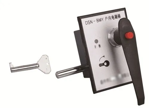
The electromagnetic lock operating voltage depends on the coil rating, control circuit, and available power supply. Switchgear electromagnetic locks support electrical interlocking in distribution cabinets and high-voltage switchgear. Their function helps prevent unauthorized or incorrect operating sequences. Engineers must match the lock's electrical specifications with the cabinet's control system. A voltage mismatch can cause unreliable movement, excessive heating, or coil damage. Therefore, selection should begin with the manufacturer's nameplate and technical documentation. Buyers should also distinguish between the voltage supplied to the control circuit and the voltage required by the locking coil. These values may differ within the same installation. Correct matching supports reliable operation and reduces unnecessary maintenance. The final selection must also comply with the switchgear's electrical design and applicable safety procedures.
Which Voltage Ratings Matter in Switchgear Electromagnetic Locks?
Three electrical ratings deserve attention during product selection: rated voltage, operating current, and power consumption. Rated voltage identifies the supply conditions specified for the coil. Operating current indicates the electrical demand during energization. Power consumption describes the electrical energy converted into heat and magnetic action. These parameters work together, so buyers should never assess voltage in isolation. A lock rated for direct current may require different internal construction from an alternating-current model. The nameplate should identify the applicable supply type and nominal voltage. Technical documentation should clarify permissible voltage variation, duty cycle, and connection requirements. If these details remain unclear, request written confirmation from the manufacturer before installation. This approach reduces commissioning errors and helps maintain dependable cabinet interlocking.
Common DC and AC Voltage Options for Electromagnetic Locks
Industrial switchgear projects use different control voltage levels according to their electrical architecture. Some electromagnetic locks operate at 24 V DC, while other designs use 48 V DC, 110 V DC, or 220 V DC. Certain models support specified AC supplies instead. These values represent possible product configurations, not universal compatibility options. A lock designed for one voltage cannot automatically operate safely at another. Direct-current supplies commonly serve control circuits in substations and industrial installations. Alternating-current supplies may appear in equipment designed around AC control power. Selection must account for the actual coil specification, available supply, and manufacturer-approved operating range. Buyers should verify both voltage and current requirements before ordering. Project drawings and technical datasheets provide the necessary evidence for making the final decision.
How Does the Control Circuit Affect Lock Voltage?
An electromagnetic locking system depends on more than its power source. Relays, auxiliary contacts, terminal blocks, and control switches determine when the coil receives power. In a switchgear cabinet, these components may connect the lock to a defined operating sequence. For example, an electrical interlock can prevent access to a compartment until specified switching conditions are satisfied. Incorrect wiring may energize the coil at the wrong time or prevent normal release. Engineers should check the circuit diagram, contact ratings, and terminal assignments before commissioning. They must also consider cable length because conductor resistance can reduce voltage at the coil. A suitable supply at the panel does not guarantee the same voltage at the lock. Measurements should therefore follow approved electrical safety procedures.
How to Match Electromagnetic Lock Operating Voltage to the Power Supply?
Correct selection starts with the lock's nameplate and the control system's documented output. Confirm whether the coil requires AC or DC, then compare its rated voltage with the supply. Next, check the manufacturer's permitted voltage tolerance and current demand. The electromagnetic lock operating voltage must remain within the specified range during normal operation. Cable resistance, terminal condition, and simultaneous loads can affect the voltage available at the coil. Engineers should calculate expected voltage drop using the cable's material, cross-sectional area, length, and load current. They should also verify the power supply's capacity under the worst expected operating conditions. Never compensate for weak locking action by arbitrarily increasing voltage. Instead, identify the cause and correct the circuit, wiring, or supply configuration.
What Happens When the Lock Receives the Wrong Voltage?
Undervoltage can prevent a coil from generating sufficient magnetic force or completing its intended movement. The lock may respond slowly, fail to engage, or behave inconsistently during repeated operations. These symptoms can resemble mechanical wear or a defective control contact. Overvoltage creates a different risk because additional electrical energy can increase coil heating. Prolonged overheating may damage insulation and shorten service life. Applying AC to a DC-only coil, or the reverse, can also produce unpredictable electrical behavior. Technicians should never assume that matching nominal voltage alone establishes compatibility. They must verify the current type, rated frequency where applicable, coil specifications, and connection diagram. When a lock behaves abnormally, isolate the equipment according to site procedures before inspection. Reliable interlocking depends on correcting the root cause rather than bypassing protective functions.
How Do Coil Resistance and Power Consumption Affect Selection?
Coil resistance and current help engineers evaluate whether a power supply can support an electromagnetic lock. For a resistive DC coil under steady-state conditions, electrical power can be estimated with \(P=UI\). If resistance is known, engineers can also use \(P=U^2/R\). Here, \(P\) represents power in watts, \(U\) represents voltage, \(I\) represents current, and \(R\) represents resistance. These calculations provide estimates rather than replacing manufacturer specifications. Coil temperature, construction, and operating conditions may influence actual performance. AC coils also require consideration of impedance and power factor, where applicable. The power supply must accommodate the lock alongside other connected loads. Engineers should check startup behavior and any specified duty-cycle restrictions. Confirming these parameters helps prevent supply overloads and supports consistent interlocking performance.
What Voltage Should Different Switchgear Applications Use?
The correct supply depends on the switchgear design, the selected lock, and the control architecture. A low-voltage distribution cabinet may use a different control supply from a substation interlocking system. Neither application determines the coil rating by itself. The following table presents illustrative selection considerations rather than universal product specifications.
| Application | Possible supply | Key verification |
|---|---|---|
| Industrial cabinet control | 24 V DC | Coil rating and supply capacity |
| DC interlocking circuit | 48 V DC | Rated voltage and cable drop |
| Substation control system | 110 V DC | Project drawings and coil compatibility |
| Specified high-voltage control circuit | 220 V DC | Manufacturer approval and insulation requirements |
| AC-powered control design | Specified AC rating | Frequency and AC coil specification |
These examples show why buyers must select the lock and supply as a matched pair. The voltage listed in a cabinet drawing may describe the control system rather than the coil itself. Consequently, engineers should trace the circuit from the supply through protective devices and control contacts to the lock terminals. They should confirm the expected voltage under load and check whether other devices share the same circuit. Procurement teams should also record the approved part specification in the bill of materials. If the project changes its control supply, the lock selection requires another compatibility check. This verification prevents assumptions based on common industry voltage levels from becoming installation errors.
A Field Example of Electromagnetic Lock Voltage Mismatch
Consider a representative commissioning scenario in an industrial switchgear room. A technician reports that a newly installed cabinet lock fails to engage consistently. The supply indicator appears normal, but the lock does not operate reliably during repeated tests. The team checks the wiring diagram and discovers that the installed coil specification does not match the intended control supply. They isolate the circuit and verify the nameplate before making any changes. A suitable replacement or an approved compatible supply must then meet the project's documented requirements. After correction, technicians test the lock's mechanical movement and electrical interlocking sequence. This scenario illustrates a common troubleshooting method, not a verified customer case. Actual diagnosis requires recorded measurements, product documentation, and site-specific evidence.
What Should Buyers Verify Before Ordering Electromagnetic Locks?
Purchasing teams should confirm electrical and mechanical requirements before approving an order. The electromagnetic lock operating voltage must match the intended control circuit and the manufacturer's rated specification. Buyers should identify the supply type, coil current, power consumption, and permissible voltage tolerance. They should also confirm mounting dimensions, locking direction, terminal arrangements, and auxiliary contact requirements. Environmental conditions deserve attention because temperature, moisture, dust, and vibration can affect equipment reliability. For switchgear applications, compatibility with the cabinet's interlocking sequence is especially important. Request a datasheet, wiring diagram, dimensional drawing, and relevant test documentation. If a project has special operating conditions, provide them to the supplier before production. Written confirmation reduces specification disputes and helps prevent mismatched products from reaching commissioning.
How Can Technicians Troubleshoot Electromagnetic Lock Voltage Problems?
A structured inspection helps technicians distinguish electrical faults from mechanical problems. Start by checking the product label and comparing it with the approved project documents. After following the required isolation and safety procedures, inspect terminal tightness, cable condition, protective devices, and control contacts. Qualified personnel can measure the supply and the voltage at the coil under appropriate operating conditions. A difference between these readings may indicate cable losses, poor connections, or excessive circuit loading. If the voltage is correct, investigate the coil condition, locking mechanism, and control sequence. Record readings and compare them with manufacturer specifications rather than relying on assumptions. Never bypass an interlock to restore production. Following the site's electrical safety procedures protects personnel and preserves the intended protective function.
A Practical Checklist for Voltage Selection and Commissioning
Before approving installation, engineers and technicians should complete a consistent set of verification tasks. This process connects procurement specifications with the actual wiring and operating conditions. It also creates a useful record for maintenance teams and future equipment replacement. The checklist below covers the main electrical and functional checks. Project-specific requirements may add further inspections or documentation.
- Confirm the lock's rated AC or DC supply.
- Match the coil voltage to the approved control circuit.
- Verify rated current, power consumption, and voltage tolerance.
- Check cable sizing, connection quality, and expected voltage drop.
- Confirm mounting dimensions and mechanical compatibility.
- Test the intended interlocking sequence under approved procedures.
- Record commissioning results and unresolved issues.
- Retain the datasheet, wiring diagram, and approved product identification.
Completing these checks helps teams identify mismatches before the equipment enters service. The final verification should compare measured conditions against the manufacturer's documented limits. Technicians should also confirm that the lock operates correctly throughout the required switching sequence. Any unexpected behavior requires investigation before acceptance. Maintenance staff benefit from retaining baseline measurements and the final wiring configuration. These records make later fault diagnosis more efficient and reduce uncertainty when components need replacement. A checklist cannot replace a risk assessment or the site's safety rules. Instead, it supports consistent execution and creates traceable evidence that the installed lock matches the approved design.
How to Verify Electromagnetic Lock Operating Voltage Before Acceptance?
Final acceptance should confirm that the installed lock matches its approved electrical and mechanical specifications. Inspect the nameplate, compare the wiring diagram, and verify the power supply configuration. Qualified technicians should measure voltage using appropriate instruments and approved safety procedures. They should also test the lock under its intended operating conditions. The electromagnetic lock operating voltage must remain within the manufacturer's specified limits during normal operation. Acceptance checks should include mechanical engagement, release behavior, and the complete interlocking sequence. Record any deviations and obtain engineering approval before accepting corrective changes. Where replacement parts are necessary, confirm their dimensions and electrical characteristics before installation. These measures support traceability and reduce the risk of recurring faults during service.